IFP-75/IFP-75HV Installation/Operation Manual — P/N LS10147-001SK-E:D 06/25/2021 71
Addressing IDPSLC Devices IDP, SK, SD and SWIFT SLC Device Installation
7.7 Addressing IDPSLC Devices
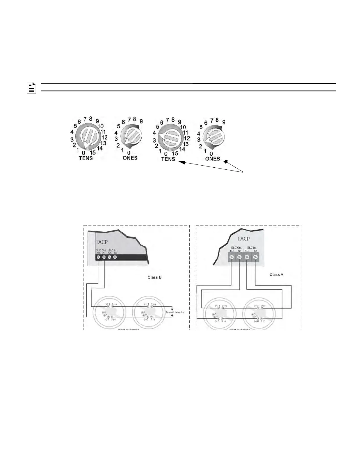
All IDP devices are addressed using the two rotary dials that appear on the device board. Use the ONES rotary dial to set the ones place in a
one or two digit number, and use the TENS rotary dial to set the tens place in a two digit number.
The IDP device addresses are handled differently than SDdevice addresses. The control panel recognizes when a IDP detector or the IDP
module is installed. For this reason, the IDP detectors can be assigned any unique address from 1 to 75, and the IDP modules can be assigned
any unique address from 1 to 75. There can be a IDP detector using address 1 and a IDP module using address 1. The zero, 0, is an invalid
address.
Example 1: To select device address 1, turn the ONES rotary dial to 1 and the TENS rotary dial to 0 as shown in Figure 7.4 .
Example 2: To select device address 42, turn the ONES rotary dial to 2 and the TENS rotary dial to 4 as show in Figure 7.4.
ik
Figure 7.4 IDPSLC Device Addressing Using Rotary Dials
7.8 SD Detector Installation
The information in this section applies to the following SD models, see Table 7.3 for the list of devices.
1. Wire the device bases as shown in Figure 7.5.
2. Set the address for each device as described in Section Figure 7.9.
.
Figure 7.5 Heat or Smoke Detector Connection to the FACP (Class B)
NOTE: Any device addressed over 50 will not be recognized by the panel.
Example 1: Device Set to 01.
Example 2: Device Set to 42.
All dials labeled for ONES
or TENS position.

 Loading...


