76 IFP-75/IFP-75HV Installation/Operation Manual — P/N LS10147-001SK-E:D 06/25/2021
Programming Overview Mapping Overview
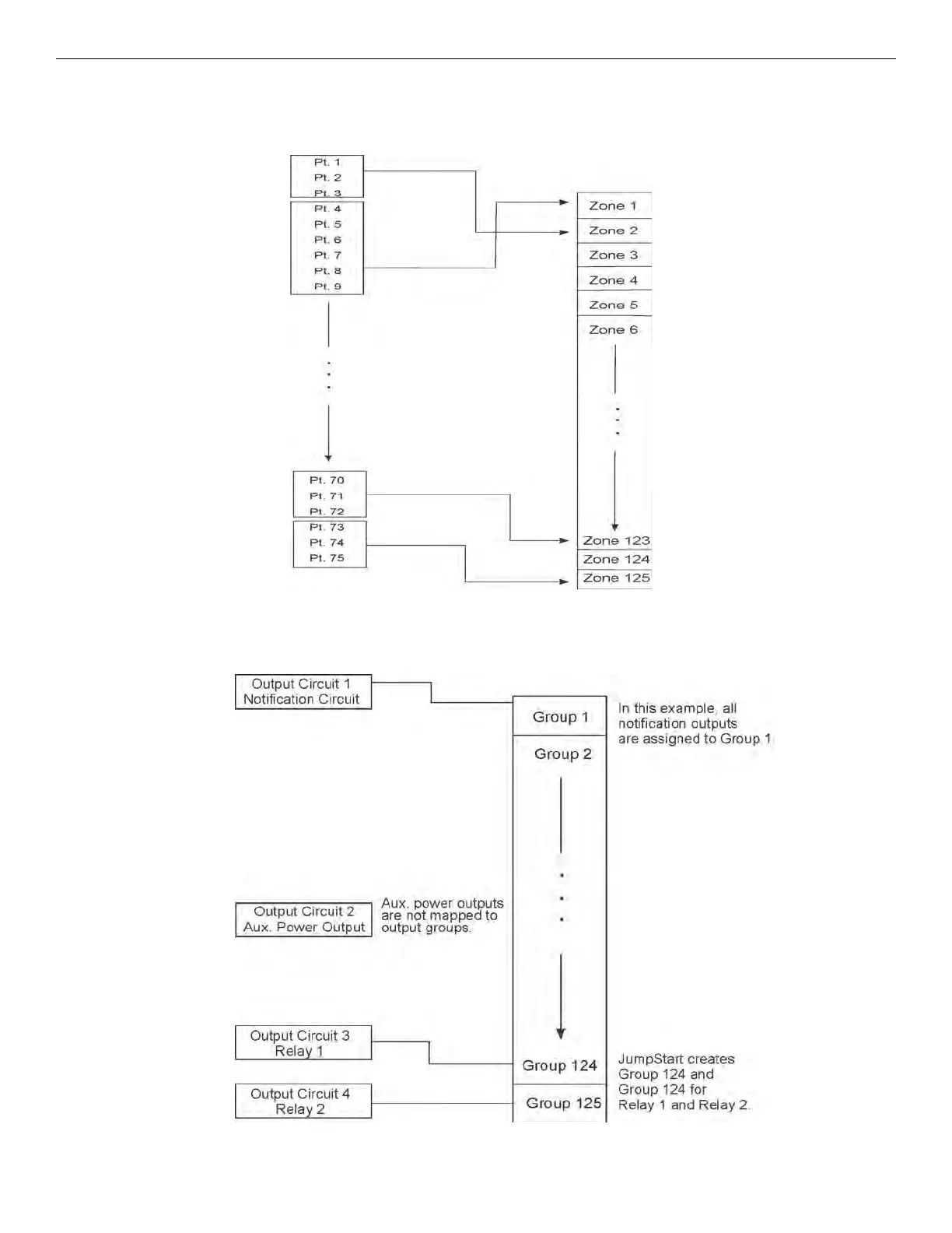
8.2.1 Input Point Mapping
The Input points are assigned to Input Zones. Any input point can be assigned to any input zone. (Input points can be assigned to one zone
only. An input point can be designated as “Unused,” which means it has not been assigned to a zone).
Figure 8.2 Input Point Assignment Example
8.2.2 Output Circuit Mapping
Figure 8.3 is a simple example showing how to assign notification and relay output circuits to groups. For an example of a simple floor
above/floor below application, see Figure 8.5.
Figure 8.3 Assigning Output Circuits to Groups (Example)

 Loading...


