18 IFP-75/IFP-75HV Installation/Operation Manual — P/N LS10147-001SK-E:D 06/25/2021
Prerequisites for Installation Board Assembly Diagram
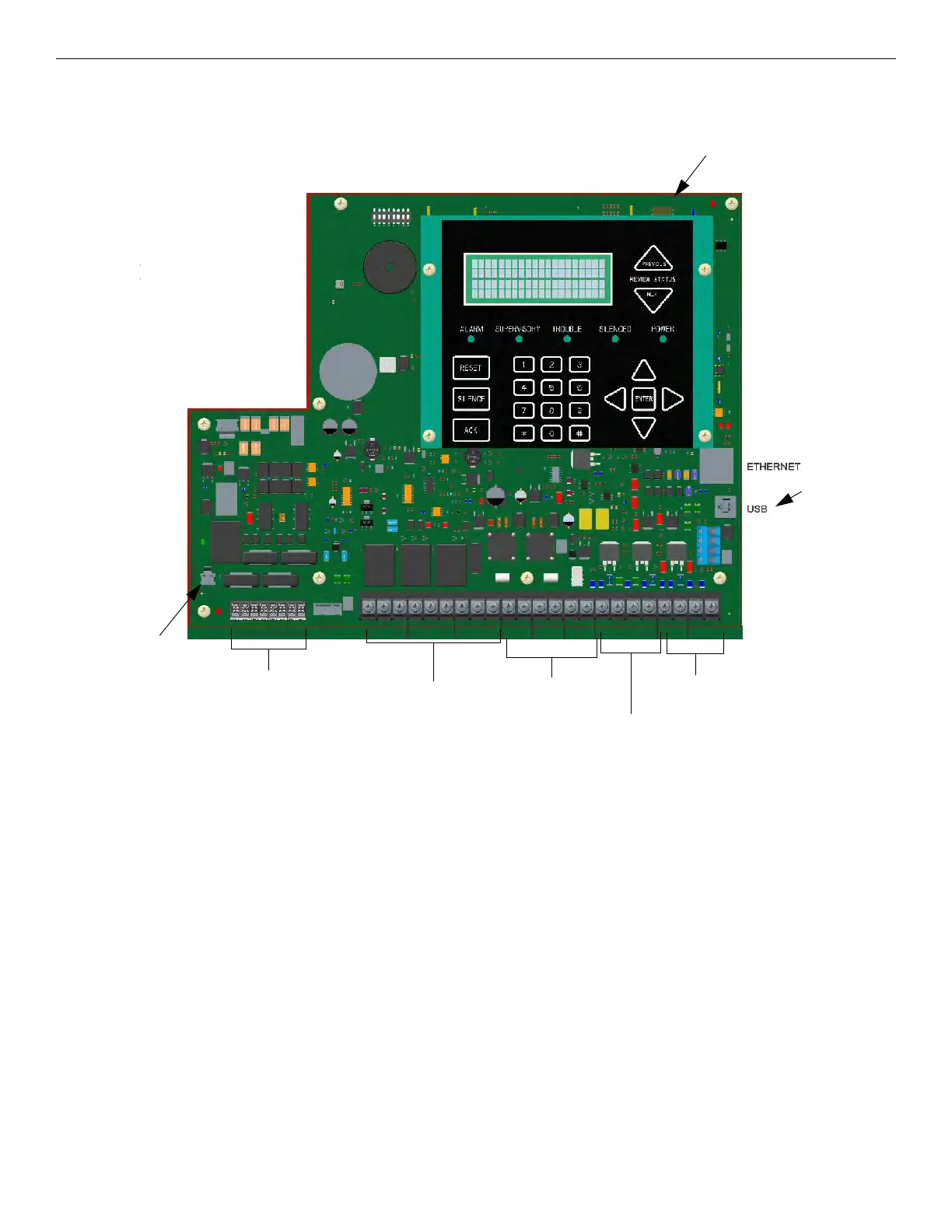
3.6 Board Assembly Diagram
Figure 3.2 Model IFP-75 Assembly
Figure 3.2 shows the circuit boards, and annunciator. If you need to remove the control board for repair, remove the three mounting screws
which hold the control board in the cabinet. Then, lift the control board out of the cabinet.
Onboard
Annunciator
NAC/Aux
Power Circuits
Phone Lines
SLC In/Out,
SLC Programming
SBUS
Connections
Battery
Connector
Program
Port
Form C
Trouble Relay
wer Input:
P-75: 120VAC 60Hz, 1.5A
P-75 240VAC, 50/60 Hz, 1A

 Loading...


