IFP-75/IFP-75HV Installation/Operation Manual — P/N LS10147-001SK-E:D 06/25/2021 29
SBUS Wiring Control Panel Installation
4. Connect the battery leads to the backup battery terminals. See Figure 4.7. Observe the proper polarity to prevent damage to the batteries
or the control panel.
5. Insert the RBB cover screws into the cover mounting holes (see Figure 4.7). Screw the cover screw 3/4 of the way into the cover
mounting hole.
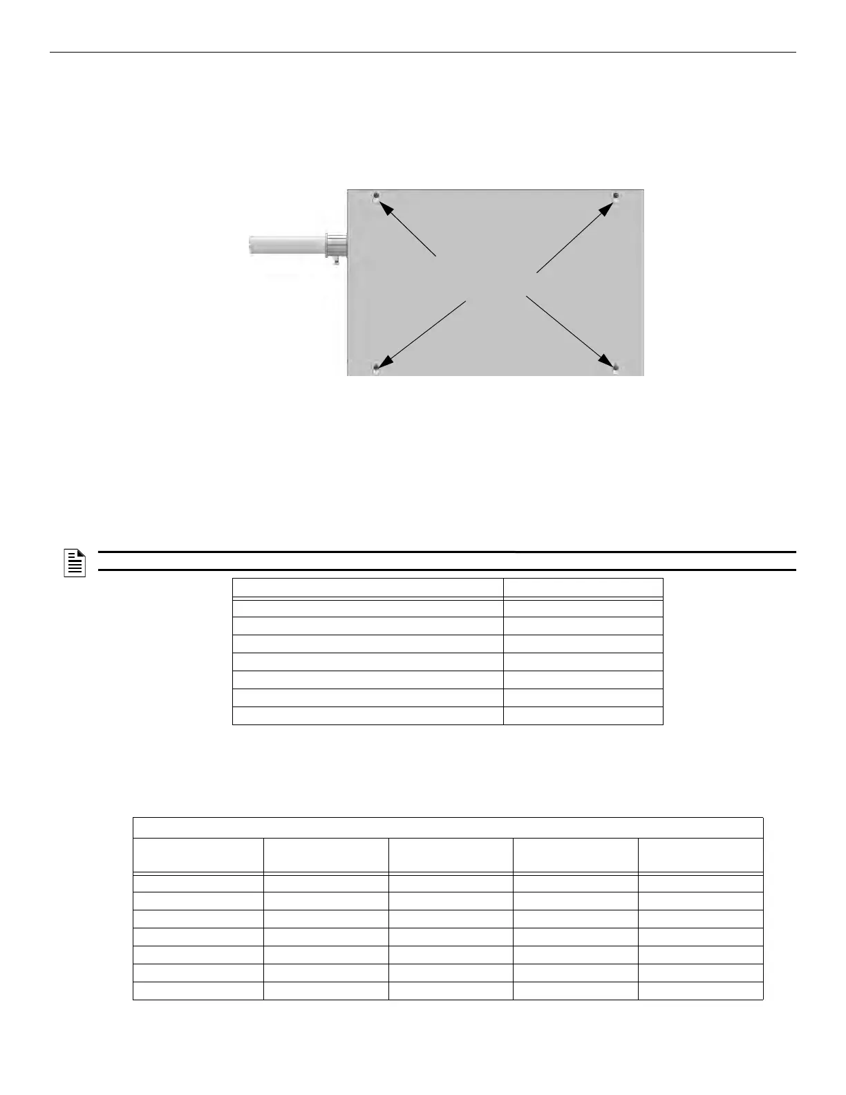
6. Align the cover plate mounting keyhole over the cover mounting screws. See Figure 4.8.
7. Slide the cover into place and tighten the cover mounting screws. See Figure 4.8.
Figure 4.8 Cover Plate Mounting Keyholes and Cover Mounting Screws Alignment
4.4 SBUS Wiring
This section contains information on calculating SBUS wire distances and the types of wiring configurations (Class B).
4.4.1 Calculating Wiring distance for SBUS modules
The following instructions will guide you in determining the type of wire and the maximum wiring distance that can be used with the control
panel SBUS accessory modules.
To calculate the wire gauge that must be used to connect SBUS modules to the control panel, it is necessary to calculate the total worst case
current draw for all modules on a single 4-conductor bus. The total worst case current draw is calculated by adding the individual worst case
currents for each module. The individual worst case values are shown in the Table 4.1.
After calculating the total worst case current draw, Table 4.2 specifies the maximum distance the modules can be located from the panel on a
single wire run. The table ensures 6.0 volts of line drop maximum. In general, the wire length is limited by resistance, but for heavier wire
gauge, capacitance is the limiting factor.
These cases are marked in the chart with an asterisk (*). Maximum length can never be more than 6,000 feet, regardless of gauge used. (The
formula used to generate this chart is shown in the note below).
Cover Plate
mounting keyholes
NOTE: Total worst case current draw on a single SBUS cannot exceed 1 amp.
Model Number Worst Case Current Draw
RA-1000, RA-100 or RA-2000 LCD Annunciator .100 amps
5824 Serial/Parallel Printer Interface Module .040 amps
5880 LED I/O Module .250 amps
5865 LED Fire Annunciator .200 amps
SK-NIC Network Interface Card .021 amps
CELL-MOD/CELL-CAB-SK .145 amps
F485C Fiber Converter .125 amps
Table 4.1 SBUS Device Current Draw
Wiring Distance: SBUS Modules to Panel
Total Worst Case
Current Draw (amps)
22 Gauge 18 Gauge 16 Gauge 14 Gauge
0.100 1852 ft. 4688 ft. * 6000 ft. * 6000 ft.
0.200 926 ft. 2344 ft. 3731 ft. 5906 ft.
0.300 617 ft. 1563 ft. 2488 ft. 3937 ft.
0.400 463 ft. 1172 ft. 1866 ft. 2953 ft.
0.500 370 ft. 938 ft. 1493 ft. 2362 ft.
0.600 309 ft. 781 ft. 1244 ft. 1969 ft.
0.700 265 ft. 670 ft. 1066 ft. 1687 ft.
Table 4.2 Wire Distances Per Wire Gauge Using Copper Wire

 Loading...


