IFP-75/IFP-75HV Installation/Operation Manual — P/N LS10147-001SK-E:D 06/25/2021 59
Setting the Panel ID for each Panel Network Networking Common Communicator List
Fiber-Optic and Twisted-Pair Wiring between Multiple Panels
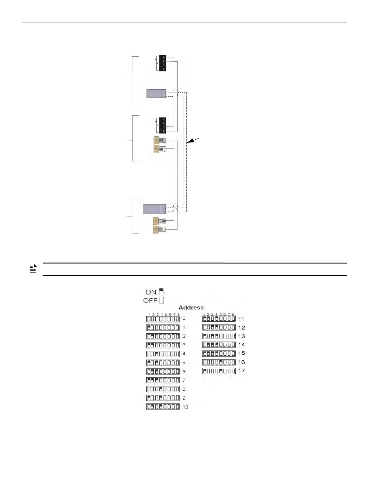
A mixture of fiber-optic cable and twisted-pair wiring between multiple panels is shown in Figure 5.9. Class X cabling is shown with a dot-
ted line.
Figure 5.9 Twisted-Pair and Fiber-Optic Combination Wiring Example
5.4 Setting the Panel ID for each Panel Network
Use the DIP switch positions 1 through 5 to set the Network ID for each panel. See Figure 5.10 below for possible DIP switch settings.
Figure 5.10 Network ID Settings
LAST
CONTROL
PANEL
SK-NIC
NEXT
CONTROL
PANEL
SK-NIC
FIRST
CONTROL
PANEL
SK-NIC
PORT 1
PORT 2
PORT 1
PORT 2
PORT 1
PORT 2
PORT 2
PORT 1
Class X
Wiring
Fiber In
Fiber Out
Fiber In
Fiber Out
NOTE: It is important that much thought is given when choosing the network IDs for each panel. It is difficult to change the IDs once the panel
programming has begun.

 Loading...


