32 IFP-75/IFP-75HV Installation/Operation Manual — P/N LS10147-001SK-E:D 06/25/2021
Control Panel Installation RA-100 Remote Annunciator Installation
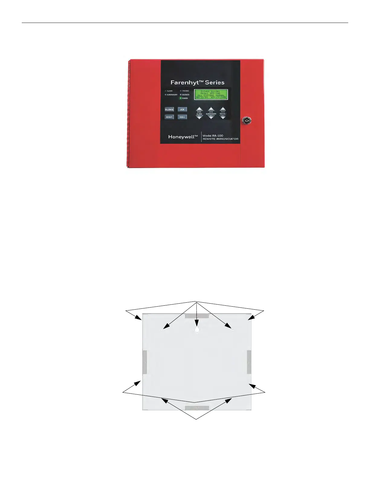
4.5 RA-100 Remote Annunciator Installation
Figure 4.11 The optional Model RA-100 Remote Annunciator, is shown in Figure 4.12. The RA-100 can be surface or flush mounted. Up
to 8 RA-100s can be added to the IFP-75System in any combination. .
Figure 4.12 Model RA-100 Remote Annunciator, Front View
RA-100 installation involves the following steps:
1. Make sure power is off at the panel.
2. Mount the RA-100 in the desired location (see Section 4.5.1).
3. Connect the RA-100 to the panel (see Section 4.5.1).
4. Use the DIP switches on the back of the RA-100 to assign an ID# to the RA-100 (see Section Section 4.11.1).
5. The new RA-100 module must be added to the system through programming. JumpStart Auto-Programming will add the module
automatically (see Section 8.1). You can also add it manually (see Section 9.2.2). Select a name, if desired.
4.5.1 Mounting the RA-100
This section of the manual describes mounting the remote annunciator. The annunciator can be flush- or surface-mounted.
Flush Mounting
This section of the manual describes flush mounting.
Follow these steps to flush mount the RA-100
1. The back box dimensions are 9-9/32” w x 8-3/8” h. The minimum depth 2". The back box can be mounted prior to the complete
installation of the RA-100 using any of the mounting holes shown in Figure 4.13.
Figure 4.13 Back Box Mounting Holes
2. Remove the knockout holes as needed for wires. See Figure 4.14 for backbox knockout locations.
Mounting Holes
Mounting Holes

 Loading...


