IFP-75/IFP-75HV Installation/Operation Manual — P/N LS10147-001SK-E:D 06/25/2021 53
Remote Station Applications Control Panel Installation
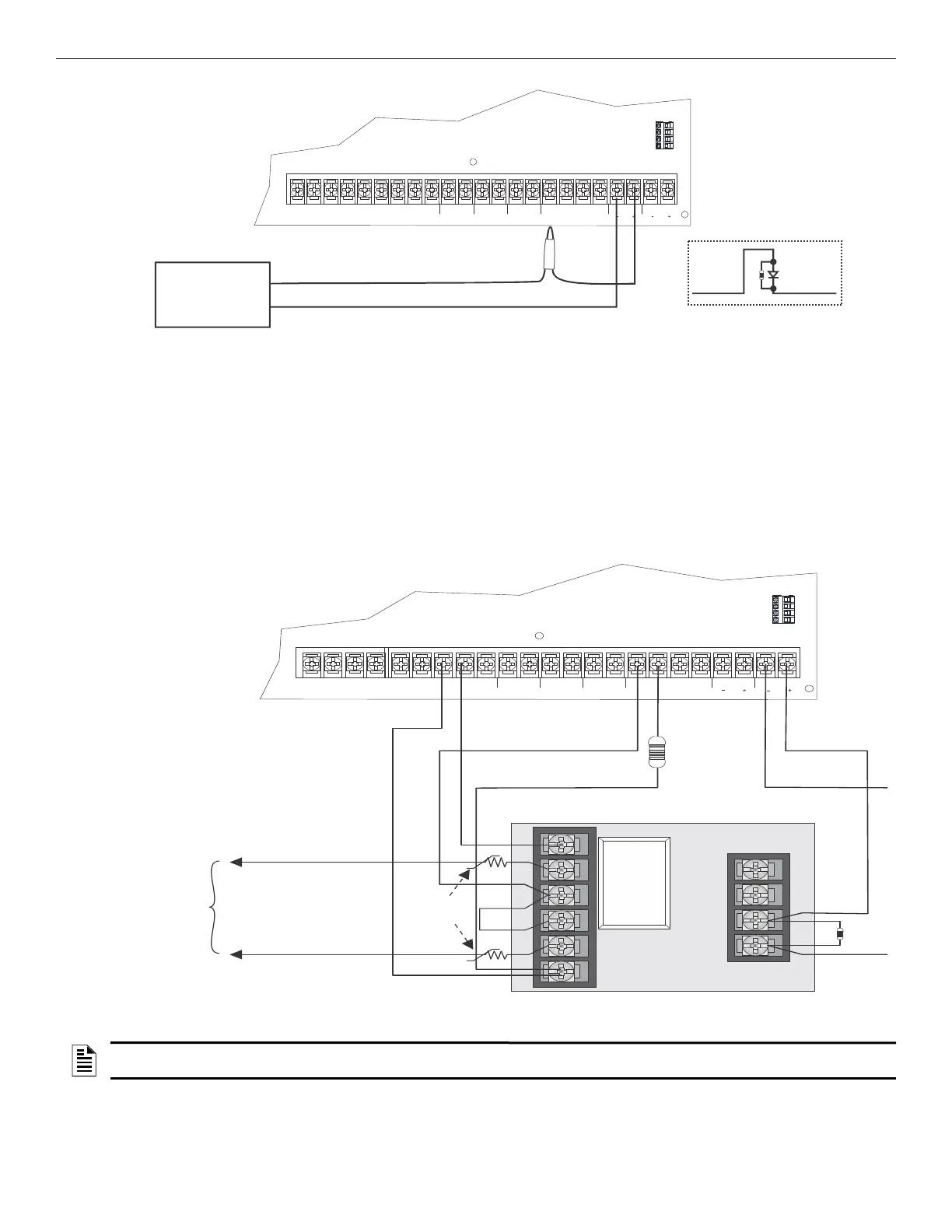
Figure 4.52 Polarity Reversal Connection Using the 7644-L8
4.15.4 Using an MR-201/T Control Relay From Air Products
When the MR-201/T control relay is wired for polarity reversal, it reports alarm and trouble events to a remote site. Alarms will override
trouble conditions and it will not be possible to reset the remote indicator until the condition is cleared and the control panel is reset.
If an alarm condition occurs, the alarm relay will close, overriding the trouble condition.
To install the MR-201/T for polarity reversal, follow the steps below:
1. Wire the MR-201/T as shown in Figure 4.53.
.
Figure 4.53 Polarity Reversal Connection Using the MR-201/T Relay
2. Program the NAC circuit for non silence NAC circuit (see Section 8.5).
1k
NO NC C
TROUBLE
RELAY 2
C NO NC
RELAY 1
C NO NC
CELLULAR AB S-S+
SLC IN
+
_
SLC OUT SLC PROG
+
_
+
_
SBUS
A
B
+
_
NAC 1
NAC 2
Control Panel
Board Assembly
Remote
Indicator
Black
White
Black
White
cellular S-
Current: 15mA max.
Operating Voltage: 24VDC nominal; 27.4 VDC max.
Resistance: 4KΩ
0 24 115 230
NO C NC NO C NC
NO NC C
TROUBLE
RELAY 2
C NO NC
RELAY 1
C NO NC
CELLULAR AB S-S+
SLC IN
+
_
SLC OUT SLC PROG
+
_
+
_
SBUS
A
B
+
_
NAC 1
NAC 2
To Remote
Receiving
Station
4.7 K
EOL
UL Listed
EOL
Intended for Connection to a
Polarity Reversal Circuit of A
Remote Station Receiving Unit
Having Compatible Rating.
UL Listed
EOL
MR-201
cellular S-
NOTE: If you need to transmit supervisories or trouble conditions, additional relay modules must be added. Use the Relay 1 to transmit
supervisory conditions. Use the trouble relay to transmit trouble conditions.

 Loading...


