34 IFP-75/IFP-75HV Installation/Operation Manual — P/N LS10147-001SK-E:D 06/25/2021
Control Panel Installation RA-100 Remote Annunciator Installation
Place a level on top of the back box, with the back box level, insert the rest of the mounting screws.
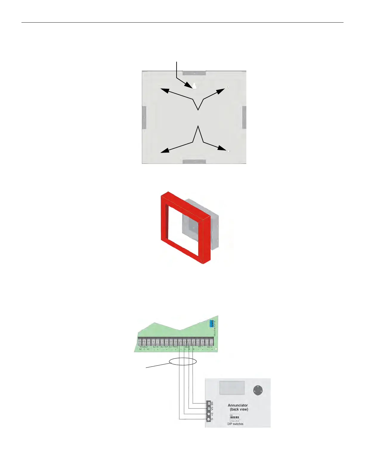
Figure 4.17 Back Box Surface Mount Holes
3. Run wires to the control panel.
4. Place the trim ring over the back box as shown in Figure 4.18.
Figure 4.18 Installing the Trim Ring
5. Attach the door assembly to the back box using the screws provided.
6. After the annunciator wiring to the panel has been completed (described in Section 4.5.1), replace the electronic assembly in the back
box. Place the bezel over the back box and tighten the set screws on the bezel.
4.5.2 RA-100 Connection to the Panel
Connect the RA-100 to the panel as shown in Figure 4.19.
Figure 4.19 Model RA-100 Connection to the Panel
Key Shaped
Mounting Hole
Back Box
mounting holes

 Loading...


