IFP-75/IFP-75HV Installation/Operation Manual — P/N LS10147-001SK-E:D 06/25/2021 33
RA-100 Remote Annunciator Installation Control Panel Installation
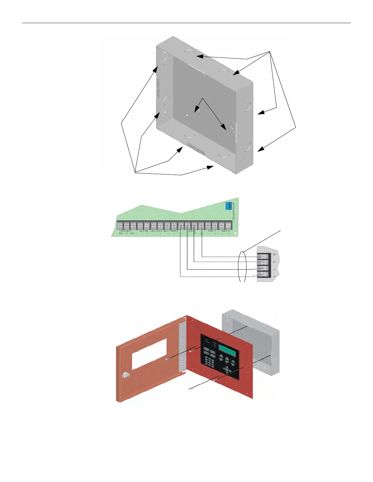
Figure 4.14 Back Box Knockout Locations
Figure 4.15 illustrates Class B configuration.
Figure 4.15 SBUS Class B Wiring
Wire the Annunciator board to the main control panel. See Figure 4.15.
3. Attach the annunciator and door assembly to back box as shown in Figure 4.16 using the supplied screws.
Figure 4.16 Attaching Annunciator/Door Assembly to Backbox
Surface Mounting
The optional Model RA-100TG/TR Trim Ring Kit is available for use when surface mounting.
1. Remove the desired knock outs. See Figure 4.14.
2. To mount the back box, insert a single screw into the key shaped mounting hole. Do not tighten all the way. See Figure 4.17.
wire knockouts
wire knockouts
ik kt

 Loading...


