IFP-75/IFP-75HV Installation/Operation Manual — P/N LS10147-001SK-E:D 06/25/2021 19
Calculating Current Draw and Standby Battery Prerequisites for Installation
3.7 Calculating Current Draw and Standby Battery
This Section is used to determine the current draw and standby battery needs if you are using IDP addressable devices (Table 3.3).
3.7.1 Current Draw Worksheet Requirements
The following steps must be taken when determining the IFP-75 current draw and standby battery requirements.
1. For the IFP-75, the worst case current draw is listed for the panel, addressable devices, and all SBUS expanders.
Fill in the number of addressable devices that will be used in the System, and compute the current draw requirements for alarm and
standby. Record this information in the Current Calculation Worksheet at Line A.
2. Add the total for the current draw for all auxiliary devices and record it in the Table at Line B.
3. Add the total for all notification appliance loads and record it in the Table at Line C.
4. For notification appliance circuits and auxiliary devices not mentioned in the manual and the current ratings, refer to the device manual.
5. Make sure that the total alarm current you calculated, including the current for the panel itself, does not exceed 2.5A. This current is the
maximum alarm current for the IFP-75 control panel.
If the current is above 2.5A, you will need to use a notification power expander(s) (such as, the 5496 NAC Expander). Use the
expander(s) to distribute the power loads, so that the IFP-75 or the power expanders do not exceed their power rating.
Refer to the Current Draw Worksheets provided with the 5496 Manual to identify the ratings that do not exceed their power
requirements.
6. Complete the remaining instructions in the Current Calculation Worksheet to determine the battery size requirements.
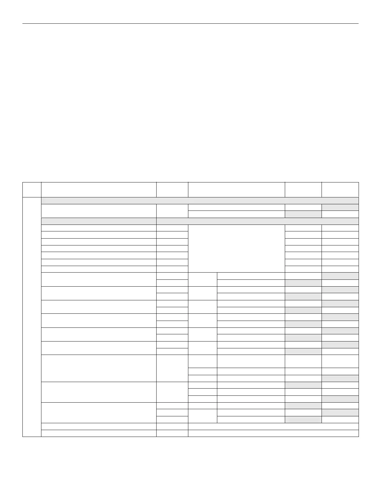
3.7.2 Current Draw Worksheet for IDP, SK SLC Devices
Use Table 3.5 to determine the current requirements during the alarm/battery standby operation when the IDP SLC devices are installed.
See the individual FACP Manual for maximum number of devices.
1
You can install up to 75IDP detectors and 75 IDP modules
1
.
D e v i c e
# of
Devices
Current per Device
Standby
Current
Alarm
Current
For each device use this formula: This column X This column = Current per number of devices.
Fire Panel (Current draw from battery) 1 Standby: 165 mA 165 mA
Alarm: 310 mA 310 mA
Addressable SLC Detectors
IDP-PHOTO Standby/Alarm: .30mA
6
mA mA
IDP-PHOTO-T mA mA
IDP-HEAT mA mA
IDP-HEAT-HT mA mA
IDP-DUCT (includes PHOTOR)
1
mA mA
IDP-ACCLIMATE mA mA
IDP-HEAT-ROR mA mA
IDP-PHOTO-W SLC Standby: 200mA mA
Alarm: 4.5mA mA
IDP-PHOTO-R-S SLC Standby: 200mA mA
Alarm: 4.5mA mA
IDP-PHOTO-T-W SLC Standby: 20mA mA
Alarm: 4.5mA mA
IDP-HEAT-W SLC Standby: 200mA mA
Alarm: 4.5mA mA
IDP-HEAT-ROR-W SLC Standby: 200mA mA
Alarm: 4.5mA mA
IDP-HEAT-HT-W SLC Standby: 200mA mA
Alarm: 4.5mA mA
IDP-BEAM (without integral test) SLC Standby/Alarm .30mA
6
mA mA
SLC Standby/Alarm: 2 mA mA mA
Aux. Pwr Standby: 2mA mA
IDP-BEAM-T (with integral test)
3
Alarm: 8.5mA mA
SLC Standby/Alarm: 2mA
Aux. Pwr Standby: 2mA mA
IDP-FIRE-CO Alarm: 8.5mA mA
SLC Standby: .30mA mA
Alarm: 7.2mA mA
DNR
5
(non-Relay) None, included with IDP-PhotoR
6
DNR
6
(with Relay) None, included with IDP-PhotoR & IDP-Relay
7
Table 3.3 Current Calculation Worksheet for IDP Devices

 Loading...


