42 IFP-75/IFP-75HV Installation/Operation Manual — P/N LS10147-001SK-E:D 06/25/2021
Control Panel Installation 5880 LED Driver Module
Printer and Output Port Options
1. From the Main Menu, select 7 for Program Menu.
2. Select 1 to access the Module.
3. Select 1 to access the Edit Module.
4. From the list that displays, select the 5824 module you want to configure.
5. Press ENTER to bypass the next two screens. A screen similar to the one shown in Figure 4.34 will display.
Figure 4.34 Selecting Printer and Output Port Options
6. Select options for the printer as needed for your installation. Most printers are parallel.
7. If you use a serial printer, use the next screen to select serial port options as required for your printer. Refer to your Printer Manual if
you need more information.
4.9 5880 LED Driver Module
The 5880 is an LED driver board that can be used in a wide variety of applications, including as an interface with most customized floor plan
annunciator boards. The 5880 can drive up to 40 LEDs and has one PZT controller. The 5880 also has eight inputs for dry contact monitor-
ing. Up to 8 5880s can be added to the IFP-75 System. The following sub-sections describe hardware installation. Refer to Section 6 for pro-
gramming information.
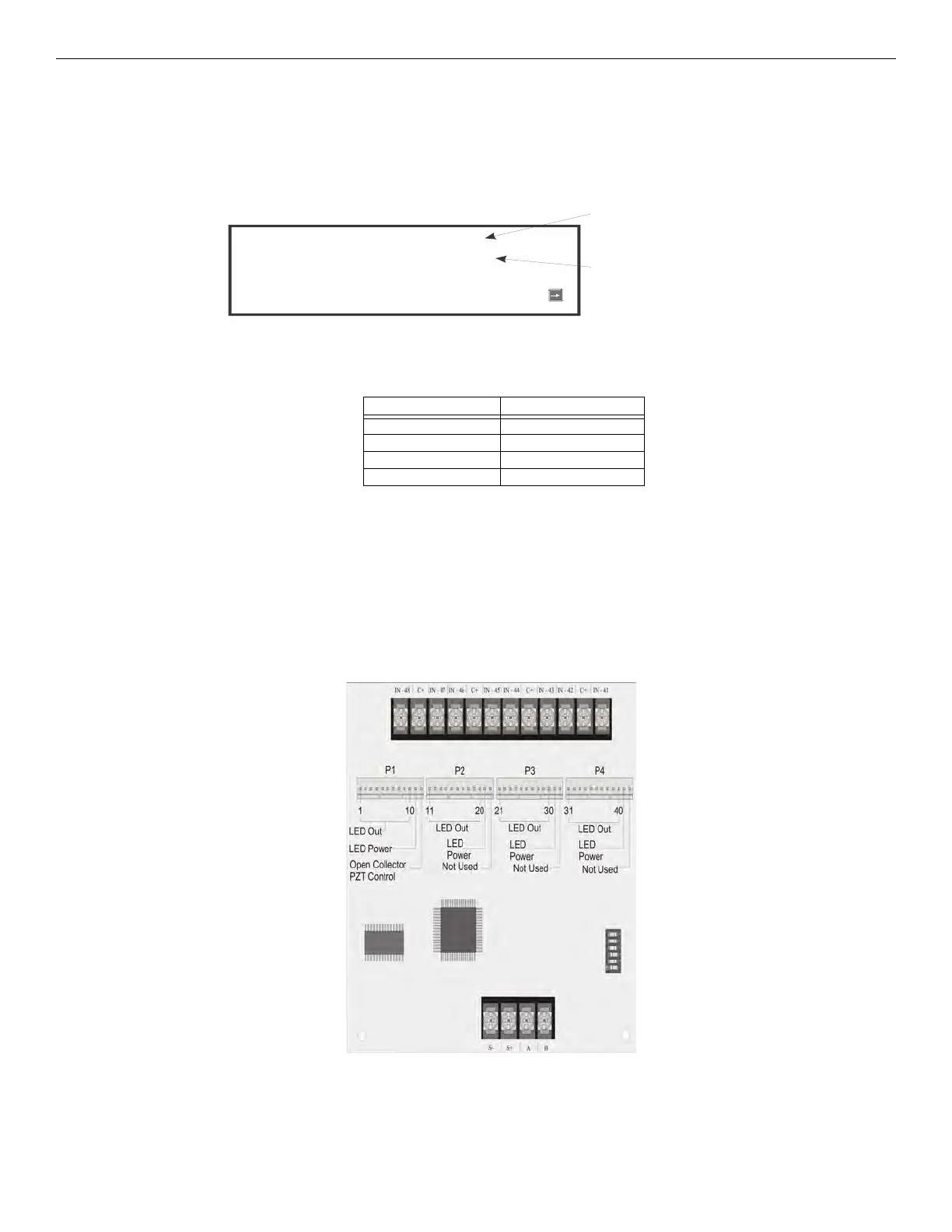
4.9.1 5880 Board Layout
Figure 4.35 illustrates the 5880 board showing the locations of the screw terminals for the connection to the panel and shows the contact
monitor wiring, (the pin connectors for connecting LEDs and the DIP switch for selecting an SBUS ID number).
Figure 4.35 5880 Board Layout
Option Choices
Baud Rate: 75 - 19200
Data Bits: 5 - 8
Stop Bits: .5, 1, 2
Parity: None, Even, Odd
Table 4.6 Printer Port Options
Select Yes if printer
should be supervised for
Out of Paper and
Offline conditions.
Select type of printer,
Parallel or Serial.
Monitor Printer=Yes
Output Port=Parallel
Event Logging= NO
More
SBUS Address
DIPs
Dry Contact Inputs - Supervised/Power Limited

 Loading...


