48 IFP-75/IFP-75HV Installation/Operation Manual — P/N LS10147-001SK-E:D 06/25/2021
Control Panel Installation Notification Appliance/Auxiliary Power Circuits
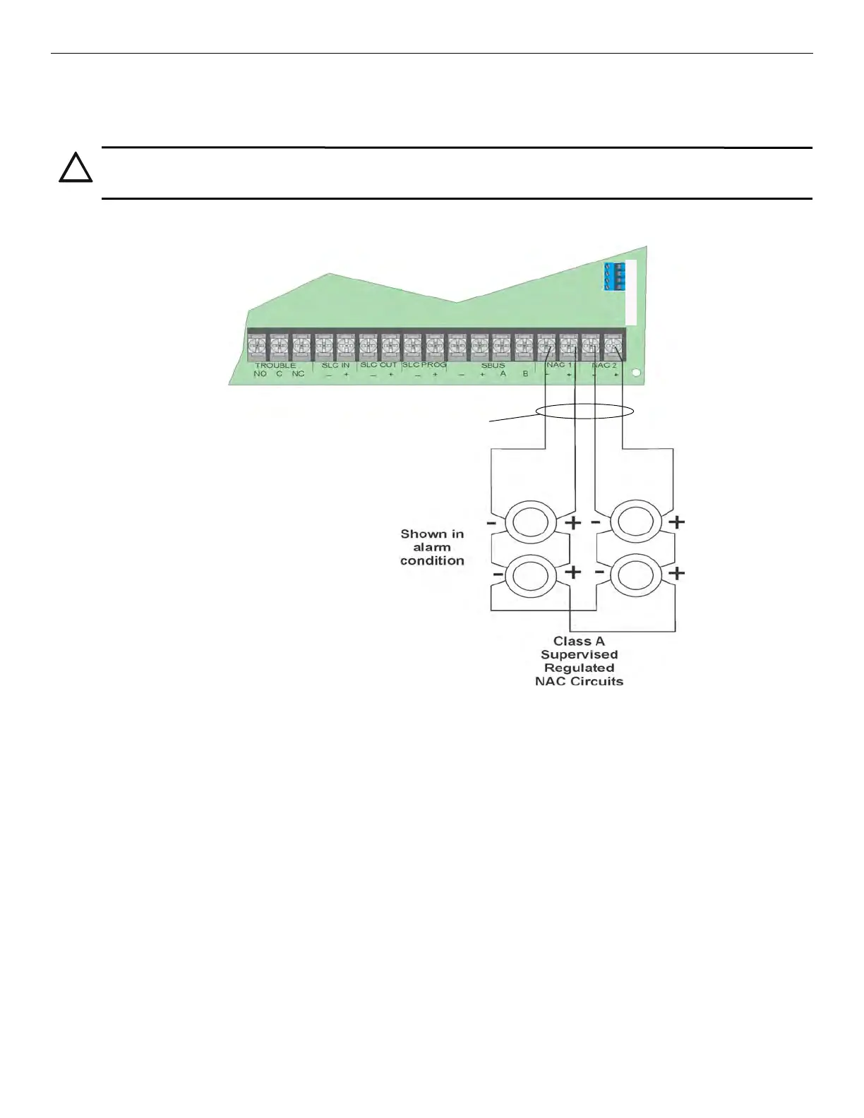
Class A Notification Wiring
You must use an appliance from the list of compatible appliances in the Appendix at the back of this manual.
To install a Class A notification appliance circuit, do the following:
1. Wire the Class A notification appliances as shown in Figure 4.46.
2. Configure the circuit for Class A in programming (see Section 8.5).
.
Figure 4.46 Class A Notification Appliance Circuit Configuration
4.13.2 Auxiliary Power Installation
NAC Circuits 1 and 2 on the control panel can be used as auxiliary power circuits. The four types of auxiliary power available are as follows:
Auxiliary power circuits are power limited. Each circuit can source up to 2.5A in an alarm condition (total current for System must not
exceed 2.5A in alarm or 1.0A for all other conditions).
To install an auxiliary power circuit, do the following steps.
1. Wire the NAC circuit(s) that will be used for the auxiliary power. See Figure 3.2 for location of NAC circuits.
2. Configure the auxiliary power output through programming (see Section 8.5).
Door Holder Power
Door holder power is used for fire door applications. When there are no alarms in the System and the panel has AC power, the door holder
circuits have 27.4 volt power present at their terminals. Any alarm will cause power to disconnect. When the System is reset, the Power will
be re-applied. If AC power is off for more than 15 seconds, the auxiliary door holder power will be disconnected to conserve the battery
backup. When AC power is restored, power is immediately restored to the door holder circuits.
CAUTION: SYSTEM SUPERVISION
FOR PROPER SYSTEM SUPERVISION DO NOT USE LOOPED WIRE UNDER TERMINALS MARKED – AND + OF THE
NAC CIRCUIT. BREAK WIRE RUNS TO PROVIDE SUPERVISION OF CONNECTIONS.
supervised
power-limited
cellular S-S+AB
• Door Holder • Constant • Resettable Power • Sounder Sync Power

 Loading...


