70 IFP-75/IFP-75HV Installation/Operation Manual — P/N LS10147-001SK-E:D 06/25/2021
IDP, SK, SD and SWIFT SLC Device Installation Wiring Requirements for SLC Devices
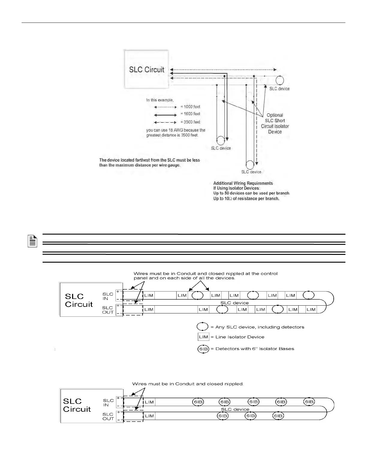
When you use T-taps, the total length of all taps and the main bus must be met in addition to the maximum distance requirements for the var-
ious wire gauge.
.
Figure 7.2 Calculating the Wire Run Length for a T-tap
7.6.3 Wiring SLC in Class A and Class X Configuration
Figure 7.3 illustrates how to wire the SLC loop for Class A installations.
.
Figure 7.3 Class A SLC Configuration
Note:
SD -Device max. Loop Resistance = 50 Ohms
IDP-Device max. Loop Resistance = 40 Ohms
SK -Device max. Loop Resistance = 40 Ohms
NOTE 1: Class A does not use the short circuit isolator devices.
NOTE 2: Class A and Class X require an isolator module as the first device placed on the in and the out loop.
NOTE 3: No t-taps allowed on the Class A and Class X SLC loops.
Note:
SD -Device max. Loop Resistance = 50 Ohms
IDP/SK -Device max. Loop Resistance = 40 Ohms

 Loading...


