IFP-75/IFP-75HV Installation/Operation Manual — P/N LS10147-001SK-E:D 06/25/2021 23
Calculating Current Draw and Standby Battery Prerequisites for Installation
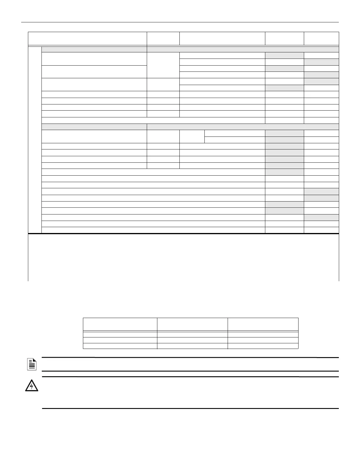
Maximum Battery Standby Load
Table 3.5 shows the maximum battery standby load for the IFP-75 based on 24 and 60 hours of standby. The standby load calculations of line
D in the Current Draw Calculation Worksheet (Table 3.5) must be less than the number shown in Table 3.5 for the battery size used and
standby hours required.
Auxiliary Devices
3
Refer to devices manual for current rating.
IPDACT-2 IP Communicator Alarm: 136 mA
mA
Standby: 93 mA mA
IPDACT-2UD IP Communicator Alarm: 155 mA mA
Standby: 98 mA mA
CELL-MOD/CELL-CAB-SK Standby: 55 mA mA
Alarm: 100 mA mA
Alarm/Standby: mA mA mA
Alarm/Standby: mA mA mA
Alarm/Standby: mA mA mA
Alarm/Standby: mA mA mA
Auxiliary Devices Current
Notification Appliance Circuits Refer to device manual for current rating.
5495/5499 Power Supply 24 VDC One input circuit: 15mA
mA
Both input circuits: 30mA
mA
Alarm: mA
mA
Alarm: mA
mA
Alarm: mA
mA
Alarm: mA
mA
Notification Appliances Current:
mA
Total current ratings of all devices in the System (line A + line B + C) mA mA
Total current ratings converted to amperes (line D x .001): A A
Number of standby hours (24 or 60 for NFPA 72, chapter 1, 1-5.2.5): H
Multiply lines E and F. Total standby AH AH
Alarm sounding period in hours. (For example, 5 minutes = .0833 hours) H
Multiply lines E and H. Total alarm AH
AH
Add lines G and I.
4
AH
Multiply by the Derating Factor x 1.25
Total ampere hours required
NOTES
Note 1: The Total does not include the isolator devices or the accessory bases.
Note 2: If you use only 24 VDC aux power, no standby or alarm current for battery calculation required, if using 24 VAC, 120 VAC or 240 VAC.
Note 3: If you use door holders, you do not need to consider the door holder current for the alarm/battery standby, because the power is removed
during that time. However, during the normal operation, the door holders draw current, and must be included in the 1.0A total current that can be
drawn from the panel.
Note 4: Use the next size battery with a capacity greater than required.
Note 5: The FACP can support 30 devices with LED’s ON. This current draw is added to the panel’s alarm current.
Device # of Devices Current per Device
Standby
Current
Alarm
Current
Table 3.4 Current Calculation Worksheet for SD Devices (Continued)
Rechargeable Battery Size
Max. Load 24hrs Standby,
5 minutes Alarm
*Max. Load for 60hrs
Standby, 5 minutes Alarm
7AH 221mA 85mA
18AH 675mA 250mA
33AH 1.1A 450mA
Table 3.5 Maximum Battery Standby Load
NOTE: *Required for NFPA 72 Auxiliary Protected Fire Alarm Systems for Fire Alarm Service (City Box) and Remote Station
Protected Fire Alarm Systems (Polarity Reversal) and Digital Alarm Communicator/Transmitter (DACT).
WARNING: BATTERIES
FARENHYT DOES NOT SUPPORT THE USE OF BATTERIES SMALLER THAN THOSE LISTED IN TABLE ABOVE. USING
A BATTERY TOO SMALL FOR THE CONFIGURATION COULD OVERLOAD THE BATTERY, RESULTING IN THE BATTERY
HAVING LESS THAN THE REQUIRED 24 HOURS STANDBY POWER. USE THE CURRENT CALCULATION WORKSHEET
TO CALCULATE THE CORRECT BATTERY AMPERES/HOUR RATING NEEDED FOR THE SYSTEM CONFIGURATION.

 Loading...


