30 IFP-75/IFP-75HV Installation/Operation Manual — P/N LS10147-001SK-E:D 06/25/2021
Control Panel Installation SBUS Wiring
Wiring Distance calculation example:
Suppose a system is configured with the following SBUS modules:
2 - Module RA-100 LCD Annunciator
1 - 5865 LED Fire Annunciator
1 - 5824 Parallel/Serial Interface
The total worst case current is calculated as follows:
Using this value, and referring to the Wiring Distance table, it can be found that the available options are:
• 370 feet maximum using 22 Gauge wire
• 938 feet maximum using 18 Gauge wire
• 1493 feet maximum using 16 Gauge wire
• 2362 feet maximum using 14 Gauge wire
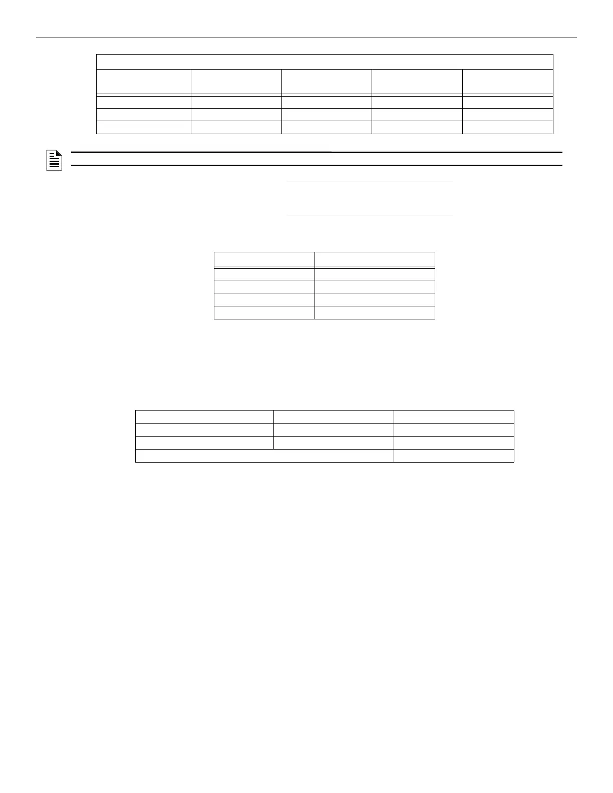
0.800 231 ft. 586 ft. 933 ft. 1476 ft.
0.900 206 ft. 521 ft. 829 ft. 1312 ft.
1.000 (Max) 185 ft. 469 ft. 746 ft. 1181 ft.
Wiring Distance: SBUS Modules to Panel
Total Worst Case
Current Draw (amps)
22 Gauge 18 Gauge 16 Gauge 14 Gauge
Table 4.2 Wire Distances Per Wire Gauge Using Copper Wire (Continued)
NOTE: The following formulas were used to generate the wire distance chart.
Maximum Resistance (Ohms) = 6.0 Volts
Total Worst Case Current Draw (amps)
Maximum Wire Length (Feet) =
(6,000 feet maximum)
Maximum Resistance (Ohms) * 500
Rpu
where: Rpu = Ohms per 1,000 feet for various wire gauges (see table below)
Table 4.3 Formula
Wire Gauge Ohms per 1000 feet (Rpu)
22 16.2
18 6.4
16 4.02
14 2.54
Table 4.4 Typical Wire Resistance Per 1000 ft. Using Copper Wire
RA-100 Current Draw = 2 x .100 amps = .200 amps
5865 Current Draw = 1 x .200 amps = .145 amps
5824 Current Draw = 1 x .040 amps = .040 amps
Total Worst Case Current Draw = .395 amps
Table 4.5 Wiring Distance Calculation

 Loading...


