IFP-75/IFP-75HV Installation/Operation Manual — P/N LS10147-001SK-E:D 06/25/2021 21
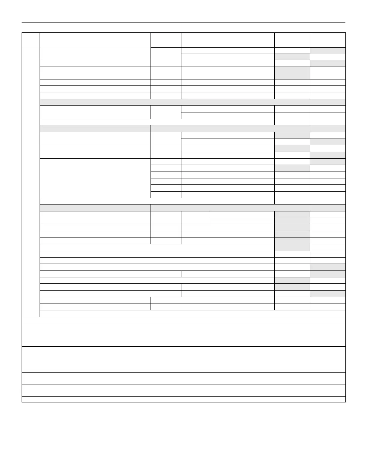
Calculating Current Draw and Standby Battery Prerequisites for Installation
5880 LED I/O Module Standby: 35 mA mA
Alarm: 200 mA mA
5883 Relay Interface (32 max.) Standby: 0 mA mA
Alarm: 220 mA
(22 mA per relay)
mA
A SK-NIC Network Interface Card (1 Max.) Standby/Alarm: 21 mA mA mA
SK-FML Fiber-Optic Multi Mode (1 Max.) Standby/Alarm: 53 mA mA mA
SK-FSL Fiber-Optic Single Mode (1 Max.) Standby/Alarm: 79 mA mA mA
Wireless Modules
Wireless Gateway Max current using external supply 40 mA mA mA
Max current SLC Power 24 mA mA mA
Total System Current
Auxiliary Devices
2
Refer to devices manual for current rating.
IPDACT-2 IP Communicator Alarm: 136 mA
mA
Standby: 93 mA mA
IPDACT-2UD IP Communicator Alarm: 155 mA mA
Standby: 98 mA mA
CELL-MOD / CELL-CAB-SK Standby: 55 mA mA
Alarm: 100 mA mA
Alarm/Standby: mA mA mA
Alarm/Standby: mA mA mA
Alarm/Standby: mA mA mA
Alarm/Standby: mA mA mA
B Auxiliary Devices Current
Notification Appliance Circuits Refer to device manual for current rating.
5495/5499 Power Supply 24 VDC One input circuit: 15 mA
mA
Both input circuits: 30 mA
mA
Alarm: mA
mA
Alarm: mA
mA
Alarm: mA
mA
C Notification Appliances Current
mA
D Total current ratings of all devices in the System (line A + line B + C) mA mA
E Total current ratings converted to amperes (line D x.001): A A
F Number of standby hours (24 or 60 for NFPA 72, chapter 1, 1-5.2.5): H
G Multiply lines E and F. Total standby AH AH
H Alarm sounding period in hours. (For example, 5 minutes =.0833 hours) H
I Multiply lines E and H. Total alarm AH
AH
J Add lines G and I.
3
AH
Multiply by the Derating Factor x 1.25
Total ampere hours required AH
NOTES
Note 1: Total does not include isolator devices or accessory bases.
Note 2: If you use door holders, you do not need to consider the door holder current for alarm/battery standby, because the power is removed during that
time. However, during the normal operation, the door holders draw current must be included in the 2.5A total alarm current (1.0A for all other conditions)
that can be drawn from the panel.
Note 3: Use the next size battery with a capacity greater than required.
Note 4: IDP-Beam-T draws a maximum of 500mA from Auxiliary power only when the test feature is used. This should be considered when determining
auxiliary power capacity but not calculated into current requirements for day to day operation.
SK-Beam-T draws a maximum of 500mA from auxiliary
power only when the test feature is used. This feature should be considered when you determine auxiliary power capacity, but are not calculated into
the current requirements for the day-to- day operation.
Note 4: The IDP-PhotoR is sold separately from the DNR. The current draw for the DNR + IDP-PhotoR is calculated by increasing the “Number of
Devices” column for each IDP-PhotoR used with a DNR.
Note 5: The DNR housing does not include a Relay circuit board. If a relay is needed, be sure to add one to the IDP-Relay & IDP-PhotoR “Number of
Devices” column for each DNR used for correct current calculations.
Note 6: The FACP can support 30 devices with LED’s ON. This current draw is added to the panel’s alarm current.
D e v i c e
# of
Devices
Current per Device
Standby
Current
Alarm
Current
Table 3.3 Current Calculation Worksheet for IDP Devices (Continued)

 Loading...


