Monitoring and Operating the Controller
90 UDC2500 Universal Digital Controller Product Manual 4/07
4.2 Operator Interface
Introduction
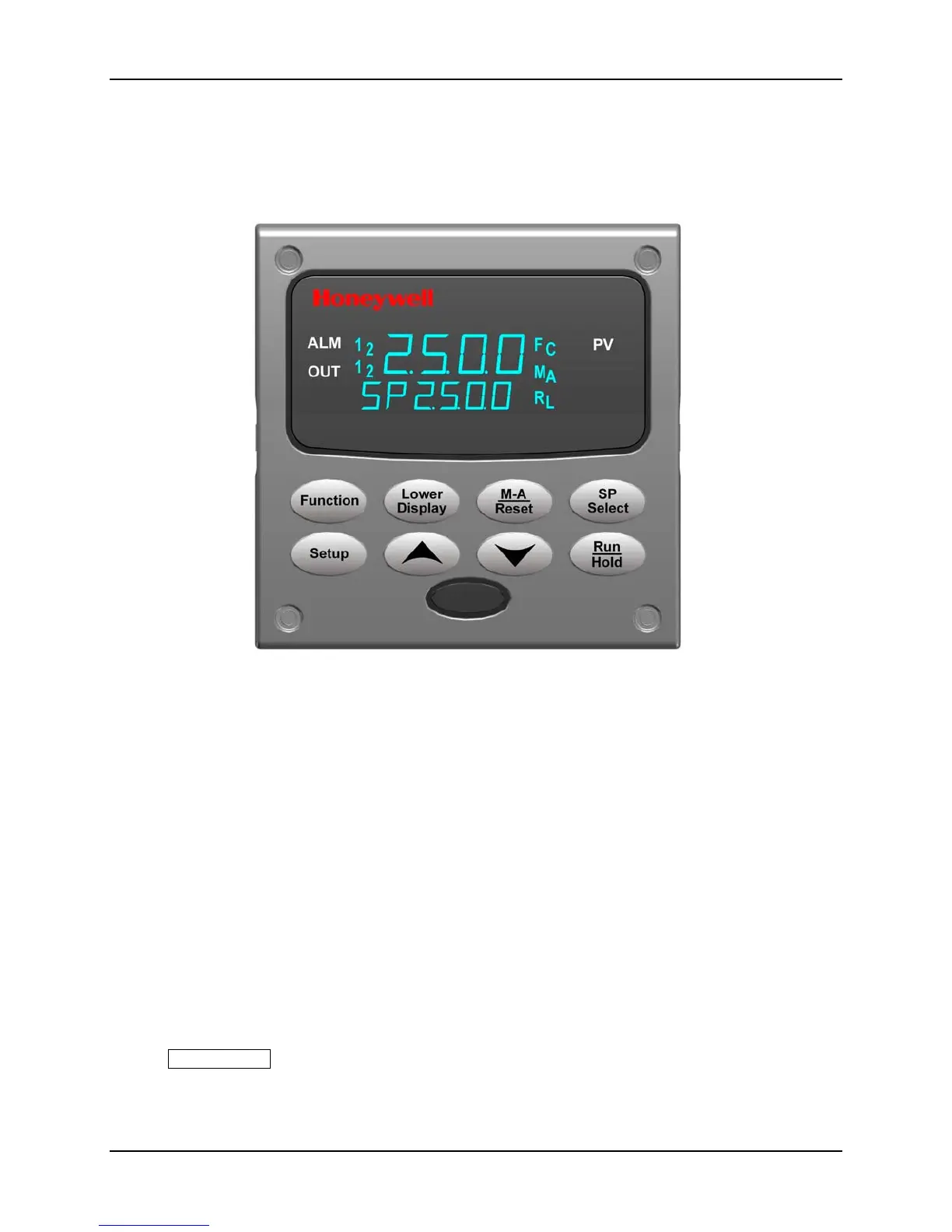
Figure 4-1 is a view of the Operator Interface.
Figure 4-1 Operator Interface
4.3 Entering a Security Code
Introduction
The level of keyboard lockout may be changed in the Set Up mode. However, knowledge
of a security code number (0 to 9999) may be required to change from one level of
lockout to another. When a controller leaves the factory, it has a security code of 0 which
permits changing from one lockout level to another without entering any other code
number.
Procedure
If you require the use of a security code, select a number from 0001 to 9999 and enter it
when the lockout level is configured as NONE. Thereafter, that selected number must be
used to change the lockout level from something other than NONE.
ATTENTION Write the number on the Configuration Record Sheet in the configuration
section so you will have a permanent record.

 Loading...


