Installation
22 UDC2500 Universal Digital Controller Product Manual 4/07
4
5
6
7
8
9
10
11
12
13
14
15
16
17
L1
L2/N
22
23
24
25
26
27
Earth
Ground
Hot
Neutral
C/DC
Line
Voltage
1
2
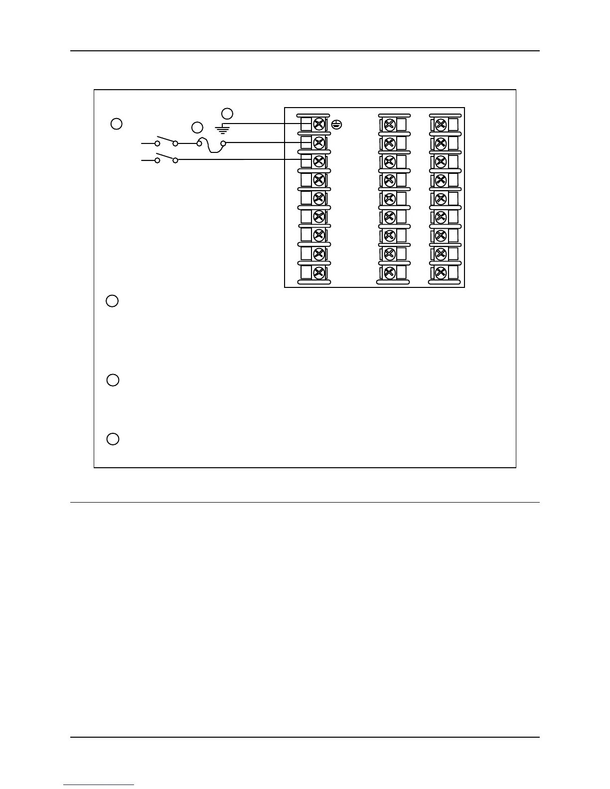
PROTECTIVE BONDING (grounding) of this controller and the enclosure in which it is
installed, shall be in accordance with National and local electrical codes. To minimize
electrical noise and transients that may adversely affect the system, supplementary
bonding of the controller enclosure to local ground using a No. 12 (4 mm
2
) copper
conductor is recommended. Before powering the controller, see “Prelimnary Checks”
in this section of the Product Manual.
1
It is the user’s responsibility to provide a switch and non-time delay (North America),
quick-acting, high breaking capacity, Type F (Europe), 1/2A, 250V fuse(s), or circuit-
breaker for 90-264 Vac applications; or 1 A, 125 V fuse or circuit breaker for 24 Vac/dc
applications, as part of the installation.
18
19
20
21
CAUTION
Applying 90-264 Vac to an instrument rated for 24 Vac/dc will severely
damage the instrument and is a fire and smoke hazard.
3
2
3
Figure 2-5 Mains Power Supply

 Loading...


