Configuration
84 UDC2500 Universal Digital Controller Product Manual 4/07
3.16 P.I.E. Tool Ethernet and Email Configuration Screens
Introduction
These screens only appear in instruments that have Ethernet Communications. Ethernet
and Email parameters can only be configured via the Process Instrument Explorer (P.I.E.
Tool
®
). The figures in this section show screen-shots of the Configuration Screens from
the PC version of the P.I.E. Tool
®
. Pocket PC Configuration Screens are generally
similar in format but smaller.
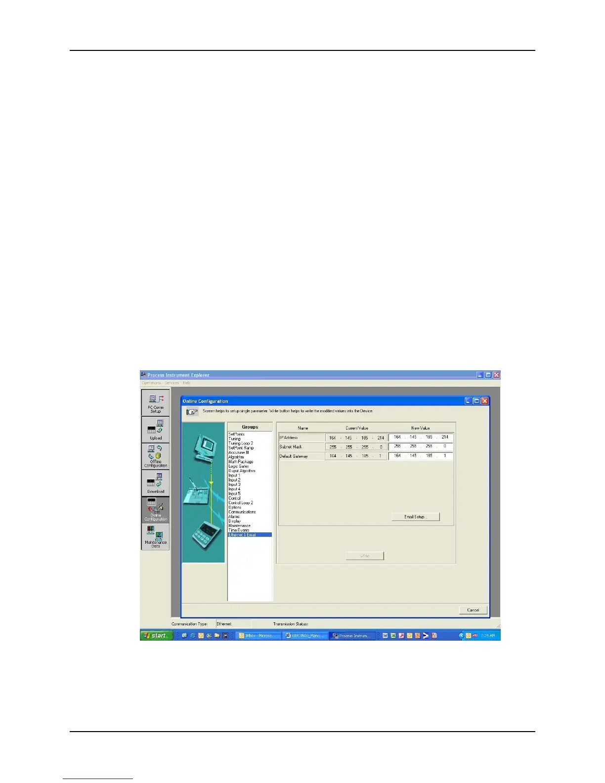
Ethernet Configuration Screen
This controller is shipped from the factory with the IP Address set to 10.0.0.2, the Subnet
Mask set to 255.255.255.0 and the Default Gateway set to 0.0.0.0. Consult your
Information Technologies (IT) representative as to how these should be configured for
your installation. The MAC address is printed on the product label located on the
instrument’s case.
These settings can be changed via the Ethernet Configuration Screen as shown in
Figure
3-1.
See Section
4.23 – Configuring your Ethernet Connection for more information.
Figure 3-1 Ethernet Configuration Screen

 Loading...


