Configuration
4/07 UDC2500 Universal Digital Controller Product Manual 59
3.10 Input 2 Set Up Group
Introduction
This data deals with various parameters required to configure Input 2.
Function Prompts
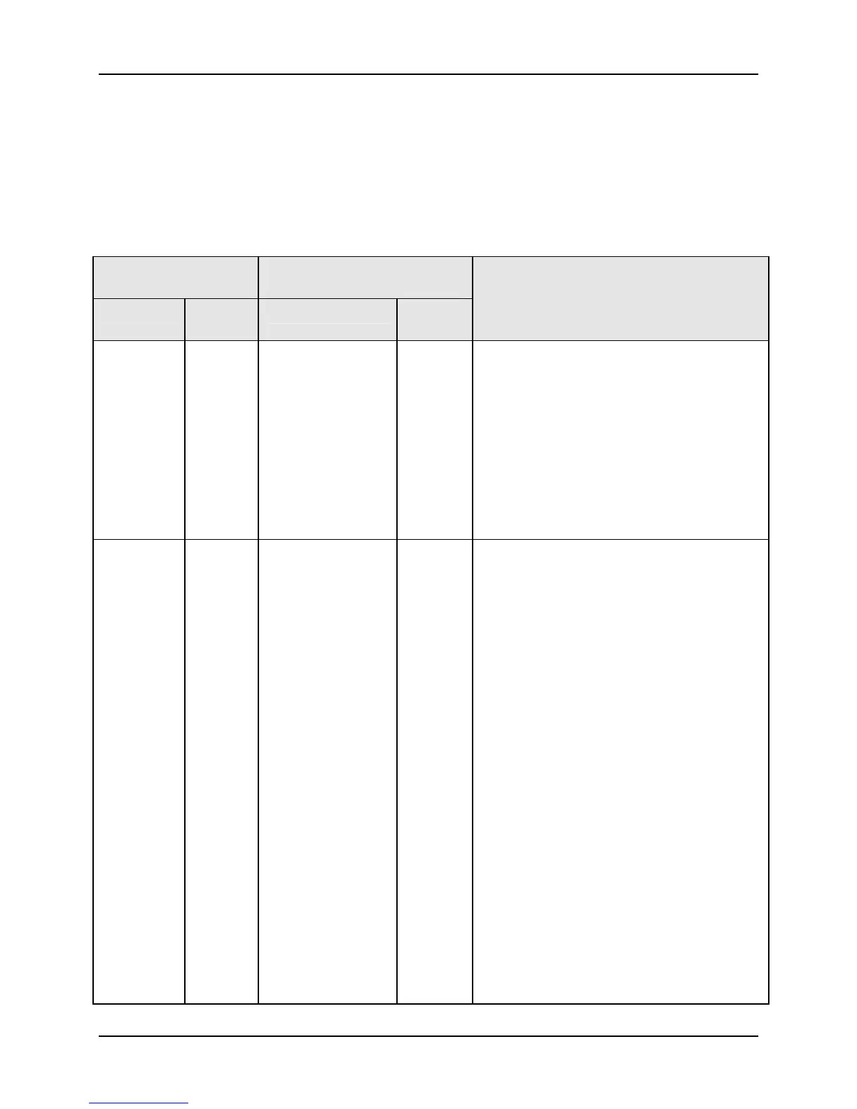
Table 3-10 INPUT2 Group (Numeric Code 700) Function Prompts
Function Prompt
Lower Display
Selection or Range of Setting
Upper Display
English Numeric
Code
English Numeric
Code
Parameter
Definition
IN2TYP 701
DIS
0-20
4-20
0-5
1-5
0-2
0
26
27
31
32
35
INPUT 2 ACTUATION TYPE – This
selection determines what actuation you are
going to use for Input 2.
DIS—Disable
0-20—0 to 20 mA (internal dropping resistor)
4-20—4 to 20 mA (internal dropping resistor)
0-5—0 to 5 Volts
1-5—1 to 5 Volts
0-2—0 to 2 Volts
XMITR2 702
B
E H
E L
J H
J M
J L
K H
K M
K L
NNMH
NNML
NIC H
NIC L
R
S
T H
T L
W H
W L
100H
100L
200
500
RADH
RADI
LIN
SrT
0
1
2
3
4
5
6
7
8
9
10
11
12
13
14
15
16
17
18
19
20
21
22
23
24
25
26
TRANSMITTER CHARACTERIZATION—
Same as Input 1 Transmitter

 Loading...


