Monitoring and Operating the Controller
4/07 UDC2500 Universal Digital Controller Product Manual 111
Set up Procedure
Use the following procedure (Table 4-18) to:
• select two sets,
• set the switch-over value,
• set tuning constant value for each set.
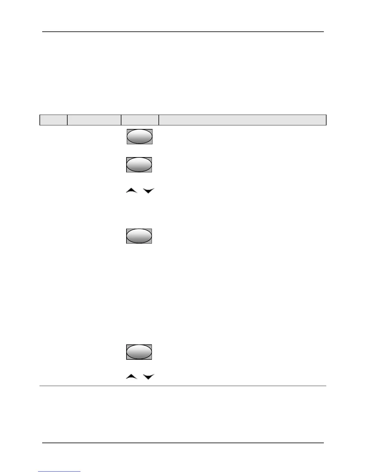
Table 4-18 Set Up Procedure
Step Operation Press Result
1
Select Control
Set-up Group
SetupSetup
Until you see:
Upper Display = SET
Lower Display = CONTRL
2
Select PID SETS
FunctionFunctionFunction
Until you see:
Upper Display = (available selections)
Lower Display = PID SETS
3
Select PID SETS
Function
or
To select the type of function. Available selections are:
ONE—1 set of constants
2 KBD—2 sets, keyboard selectable
2 PR—2 sets, auto switch at PV value
2 SP—2 sets, auto switch at SP value
4
Set Tuning
Values for Each
Set
FunctionFunctionFunction
Refer to “TUNING” Set up group, subsection
3.4 and set the
following tuning parameters:
PB or GAIN*
RATE T*
I MIN or I RPM*
CYCT1 or CTIX3*
PB2 or GAIN2**
RATE 2T**
I2MIN or I2RPM**
CYC2T2 or CT2X3**
*PIDSET1 will be used when PV or SP, whichever is
selected, is greater than the switchover value.
**PIDSET2 will be used when PV or SP, whichever is
selected, is less than the switchover value.
5
Set Switchover
Value for 2PR or
2SP Selection
FunctionFunctionFunction
Until you see:
Upper Display = (the switchover value)
Lower Display = SW VAL
or
To select the switchover value in the upper display.

 Loading...


