Input Calibration
146 UDC2500 Universal Digital Controller Product Manual 4/07
5.6 Input 2 Set Up Wiring
0 to 20 mA or 4 to 20 mA Inputs – Input 2
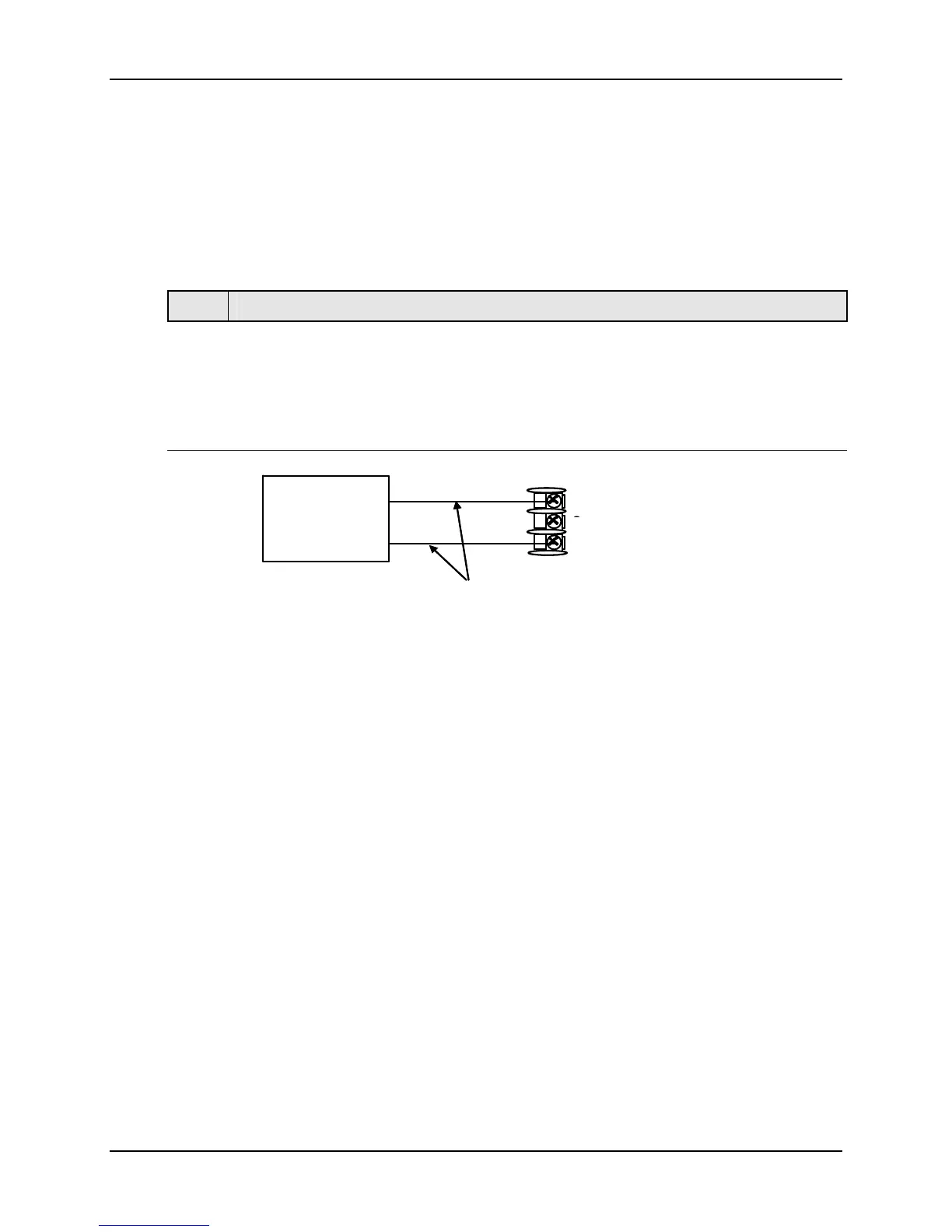
Refer to Figure 5-8 and wire the controller according to the procedure given in Table
5-13.
Table 5-11 Set Up Wiring Procedure for 0 to 20 mA or 4 to 20 mA Inputs –
Input 2
Step Action
1
Connect the copper leads from the calibrator to the Input #2 terminals as shown in
Figure 5-8.
2
Place current source at zero before switching on.
3
Do not switch current source ON/OFF while connected to the instrument.
25+
26 (no connection)
27-
Copper Leads
Equal Length
Current
Source
+
_
25+
26 (no connection)
27-
Copper Leads
Equal Length
Current
Source
+
_
Figure 5-8 Wiring Connections for 0 to 20 mA or 4 to 20 mA Input – Input 2

 Loading...


