Installation
30 UDC2500 Universal Digital Controller Product Manual 4/07
Table 2-7 Terminals for connecting a UDC to a MDI Compliant Hub or Switch
UDC Terminal UDC Signal Name RJ45 Socket Pin # Switch Signal
Name
Position 14 Shield Shield Shield
Position 15 RXD- 6 TXD-
Position 16 RXD+ 3 TXD+
Position 17 TXD- 2 RXD-
Position 18 TXD+ 1 RXD+
Table 2-8 shows how to connect a UDC directly to a PC utilizing a straight-through cable
(wiring the UDC cable this way makes the necessary cross-over connections)
Table 2-8 Terminals for connecting a UDC directly to a PC utilizing a straight-
through cable
UDC Terminal UDC Signal Name RJ45 Socket Pin # PC Signal Name
Position 14 Shield Shield Shield
Position 15 RXD- 2 TXD-
Position 16 RXD+ 1 TXD+
Position 17 TXD- 6 RXD-
Position 18 TXD+ 3 RXD+
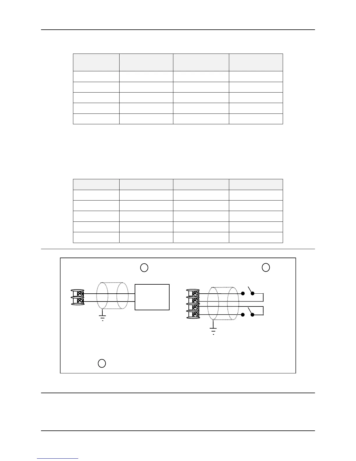
12
13
+
uxiliar
Load
0 - 1000
Connect shield
to ground at one
end only.
1
1
uxiliary Output and Digital Input 2 are mutually exclusive.
Auxiliary Output
10
11
+
Digital
Input #1
Connect shield
to ground at one
end only.
Digital Inputs
1
12
13
+
Digital
Input #2
Figure 2-17 Auxiliary Output and Digital Inputs Option Connections

 Loading...


