Output Calibration
4/07 UDC2500 Universal Digital Controller Product Manual 155
Procedure
The procedure for calibrating the auxiliary output is listed in Table 6-4. The numeric
codes are also listed.
Make sure “LOCK” in the Tuning Set Up group is set to “NONE” (see Subsection 3.4).
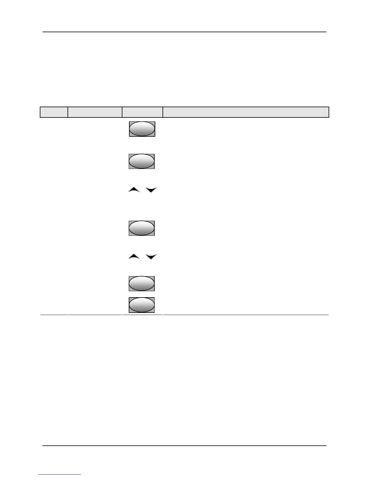
Table 6-4 Auxiliary Output Calibration Procedure
(Numeric Code 50000)
Step Operation Press Result
1
Enter Calibration
Mode
SetupSetup
until you see
Upper Display = CAL ( - - - - )
Lower Display = AUXOUT (50000)
2
Calibrate 0 %
FunctionFunctionFunction
You will see:
Upper Display = A Value
Lower Display = ZROVAL (50001)
or
until the desired 0 % output is read on the milliammeter,
use the values shown below depending on the action of
your controller. Normally, this will be the setting that
produces 4 mA.
3
Calibrate 100 %
FunctionFunctionFunction
To store the 0 % value you will see:
Upper Display = A Value
Lower Display = SPNVAL (50002)
or
until the desired 100 % output is read on the milliammeter. .
Normally, this will be the setting that produces 20 mA.
4
FunctionFunctionFunction
The controller stores the span value.
Exit the
Calibration Mode
Lower
Display
Lower
Display
Lower
Display
To exit the calibration mode.

 Loading...


