Modbus Read, Write and Override Parameters plus Exception Codes
4/07 UDC2500 Universal Digital Controller Product Manual 203
10.7.5 Output Algorithms
Table 10-13 lists all the register addresses and ranges or selections for the function
parameters in Set-up Group Output.
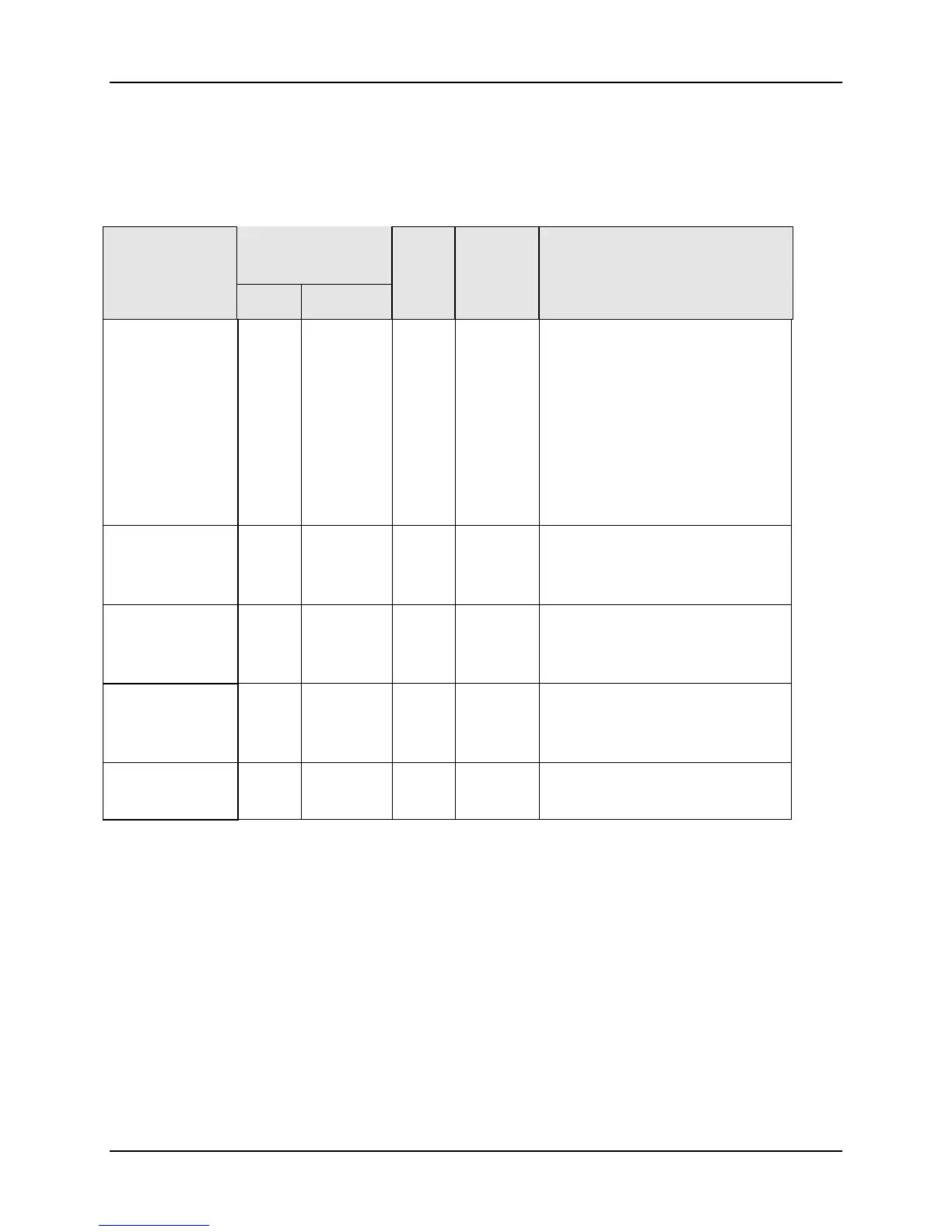
Table 10-13 Set-up Group – Output
Parameter
Description
Register
Address
Data
Type
Access Data Range or
Enumerated Selection
Hex Decimal
Output
Algorithm
00A0 160 INT R/W 0 = Time Simplex
1 = Not Used
2 = Current Simplex
3 = Three Position Step or
Position Proportioning
4 = Time Duplex
5 = Current Duplex
6 = Current/Time Duplex
7 = Time/Current Duplex
Relay Cycle
Time
Increments
00BE 190 INT R/W 0 = 1 second increments
1 = 1/3 second increments
Motor Time for
Three Position
Step
004B 075 INT R/W 5 to 1800 seconds
Current Range
for Current
Duplex
0099 153 INT R/W
0 = Full (100%)
1 = Split (50%)
Current Output
Range
00EA 235 INT R/W
0 = 4-20 mA
1 = 0-20 mA

 Loading...


