Input Calibration
4/07 UDC2500 Universal Digital Controller Product Manual 137
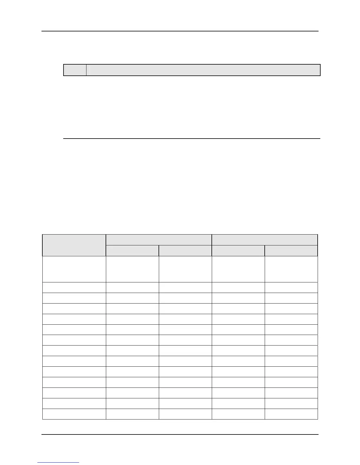
Calibration Steps
Use the following steps when calibrating an input.
Step Action
1
Find the minimum and maximum range values for your PV input range from
Table 5-1.
2
Disconnect the field wiring and find out what equipment you will need to calibrate.
3
Wire the calibrating device to your controller according to the set up wiring instructions
for your particular input (Subsection
5.4 or 5.6).
4
Follow the calibration procedure given for Input #1 or Input #2 (Subsection
5.5 or 5.7).
5.2 Minimum and Maximum Range Values
Select the Range Values
Calibrate the controller for the minimum (0 %) and maximum (100 %) range values of
your particular input type. Two input controllers will need to have each input calibrated
separately.
Select the Voltage, Current or Resistance equivalents for 0 % and 100 % range values
from Table 5-1 and Table 5-2. Use these values when calibrating your controller.
Table 5-1 Voltage, Milliamp and Resistance Equivalents for Input 1 Range Values
PV Input Range Range Values Sensor Type
°F °C 0 % 100 %
Thermocouples
(per ITS-90)
B
0 to 3300 –18 to 1816 –0.100 mV 13.769 mV
E
–454 to 1832 –270 to 1000 –9.835 mV 76.373 mV
E (low)
–200 to 1100 –129 to 593 –6.472 mV 44.455 mV
J
0 to 1600 –18 to 871 –0.886 mV 50.060 mV
J (med)
20 to 900 –7 to 482
–0.334 mV
26.400 mV
J (low)
20 to 550 –7 to 288 –0.334 mV 15.650 mV
K
0 to 2400 –18 to 1816 –0.692 mV 52.952 mV
K (med)
–20 to 1200 –29 to 649 –1.114 mV 26.978 mV
K (low)
–20 to 750 –29 to 399 –1.114 mV 16.350 mV
NiMo-NiCo (NM90)
32 to 2500 0 to 1371 0.000 mV 71.773 mV
NM90 (low)
32 to 1260 0 to 682 0.000 mV 31.825 mV
Nicrosil-Nisil (Nic)
0 to 2372 –18 to 1300 –0.461 mV 47.513 mV
Nic (low)
0 to 1472 –18 to 800 -0.461 mV 28.455 mV
R
0 to 3100 –18 to 1704 –0.090 mV 20.281 mV

 Loading...


