Modbus Read, Write and Override Parameters plus Exception Codes
4/07 UDC2500 Universal Digital Controller Product Manual 211
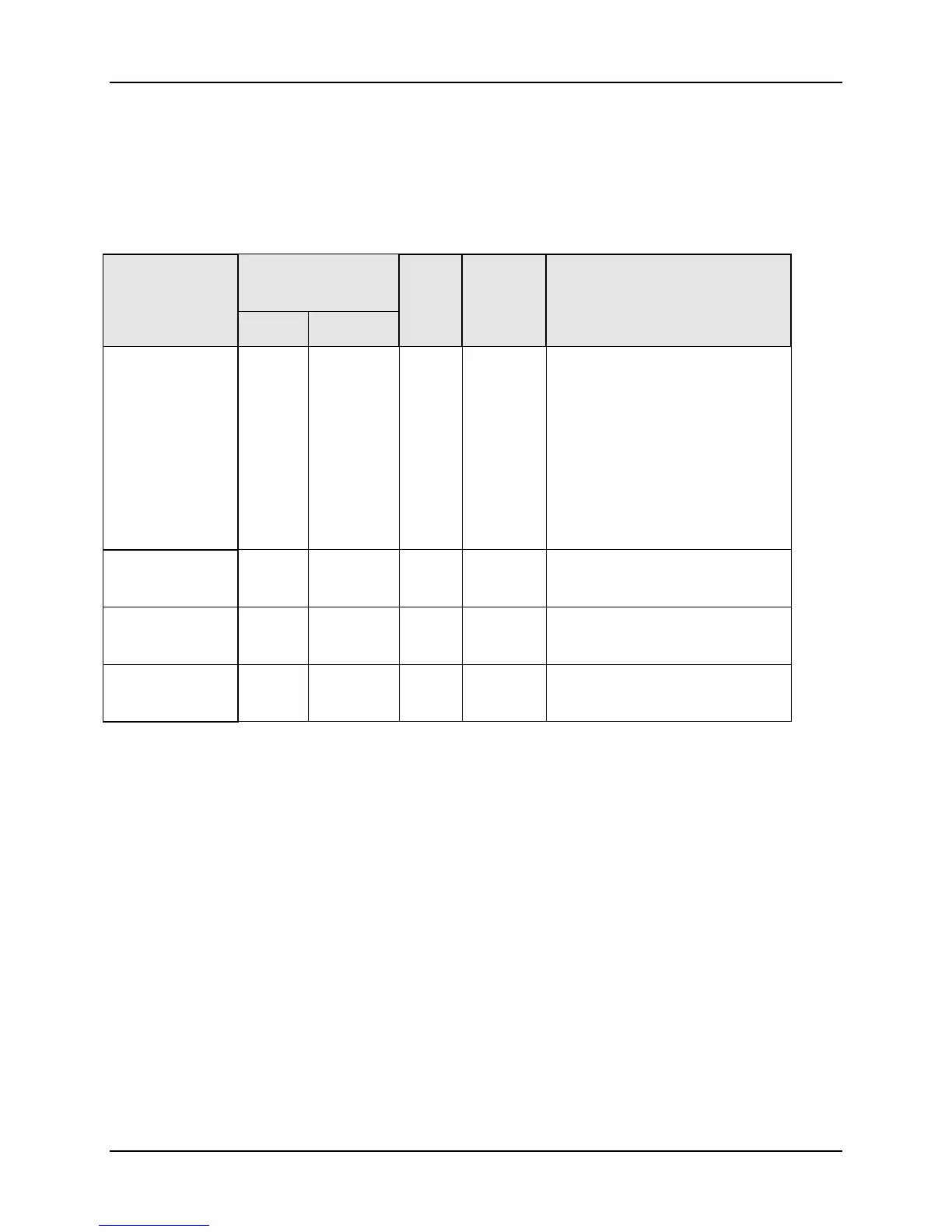
10.7.9 Options
Table 10-18 lists all the register addresses and ranges or selections for the function
parameters in Set-up Group Options.
Table 10-17 Set-up Group – Options
Parameter
Description
Register
Address
Data
Type
Access Data Range or
Enumerated Selection
Hex Decimal
Auxiliary
Output *
0086 134 INT R/W
0 = None
1 = Input 1
2 = Input 2
3 = PV
4 = Deviation
5 = Output
6 = Setpoint
7 = LSP 1
8 = LSP 2
Low Scaling
Factor
0031 049 FP R/W Within the range of the
selected variable in ID 134
High Scaling
Factor
0032 050 FP R/W Within the range of the
selected variable in ID 134
Auxiliary
Output Range
00EC 236 INT R/W
0 = 4-20 mA
1 = 0-20 mA

 Loading...


