EasyManuals Logo

Honeywell UDC2500 User Manual

Honeywell UDC2500
243 pages
To Next Page IconTo Next Page
To Previous Page IconTo Previous Page
Page #139 background imageLoading...
Page #139 background image
Monitoring and Operating the Controller
4/07 UDC2500 Universal Digital Controller Product Manual 125
4.22 P.I.E. Tool Maintenance Screens
Introduction
This controller uses special P.I.E. Tool
®
Maintenance Screens which allow remote access
and access to functions not accessible via the controller’s display and keyboard. The
figures in this section show screen-shots of the Maintenance Screens from the PC version
of the P.I.E. Tool
®
. Pocket PC Maintenance Screens are generally similar in format but
smaller.
ATTENTION
Your instrument may not have all of the screens and parameters shown in this section.
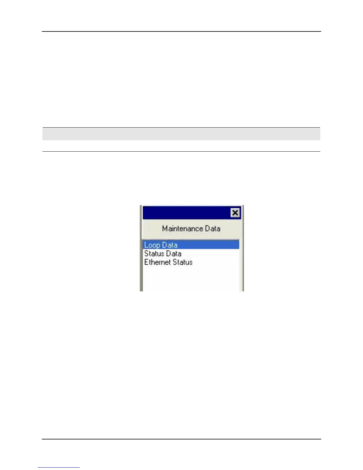
Loop Data
Select Loop Data from the Maintenance Data menu.
Figure 4-5 Maintenance Data Menu

Table of Contents

Other manuals for Honeywell UDC2500

Questions and Answers:

Question and Answer IconNeed help?

Do you have a question about the Honeywell UDC2500 and is the answer not in the manual?

Honeywell UDC2500 Specifications

General IconGeneral
TypeUniversal Digital Controller
Alarm RelaysUp to 2 alarm relays
CommunicationRS485 Modbus RTU
MountingPanel Mount
DisplayDual 4-digit LED
Input TypesThermocouple, RTD, mA, V
Control ModesOn/Off, PID
Output TypesRelay, mA, V
Power Supply100-240 VAC, 24V DC
Dimensions96x96x132 mm

Related product manuals