Installation
4/07 UDC2500 Universal Digital Controller Product Manual 31
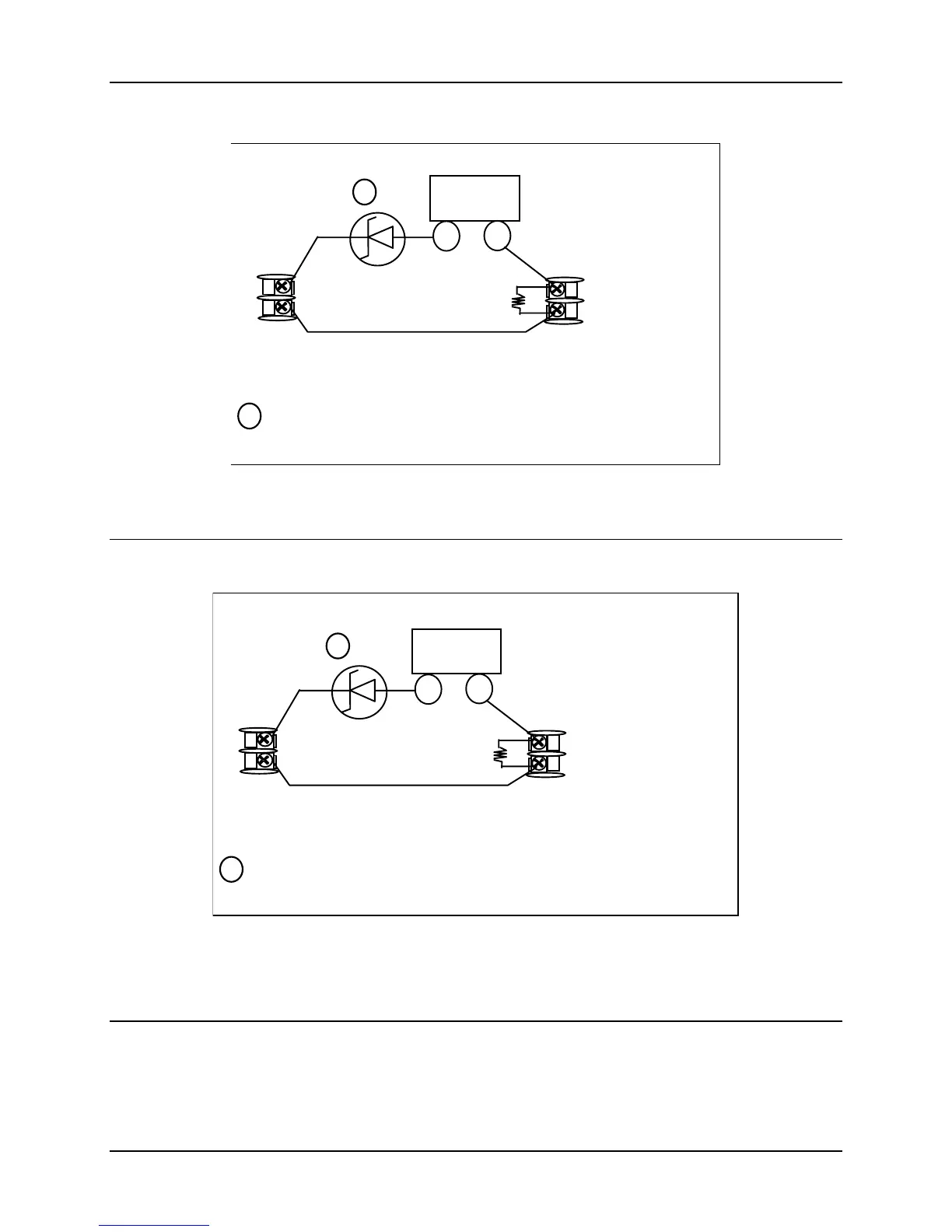
Configure:
2S1TY = NONE
2S2TY = NONE
2 Wire Transmitter
+
INPUT 1OUTPUT 3
250
26 +
27 -
5 +
6 -
If necessary, install a zener diode here to reduce voltage at the
transmitter. A 1N4733 will reduce the voltage at the transmitter to
approximately 25 Vdc.
1
1
Figure 2-18 Transmitter Power for 4-20 mA — 2 wire Transmitter Using Open
Collector Alarm 2 Output
2 Wire Transmitter
+
INPUT 1
UXILIARY OUTPUT
250
26 +
27 -
12 +
13 -
Configure:
AUXOUT = OUT
uxiliary Output Calibration
ZEROVAL = 4095
SPANVAL = 4095
If necessary, install a zener diode here to reduce voltage at the
transmitter. A 1N4733 will reduce the voltage at the transmitter to
approximately 25 Vdc.
1
1
Figure 2-19 Transmitter Power for 4-20 mA — 2 Wire Transmitter
Using Auxiliary Output

 Loading...


