Modbus Read, Write and Override Parameters plus Exception Codes
202 UDC2500 Universal Digital Controller Product Manual 4/07
10.7.4 Algorithm
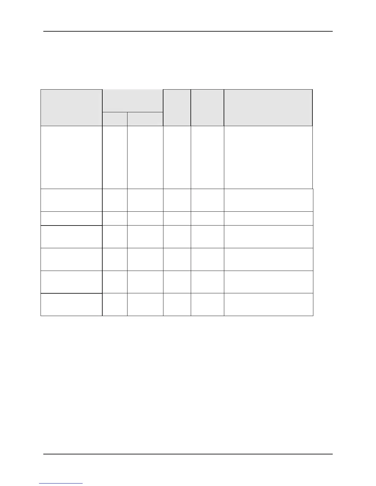
Table 10-12 lists all the register addresses and ranges or selections for the function
parameters in Set-up Group Algorithm.
Table 10-12 Set-up Group – Algorithm
Parameter
Description
Register
Address
Data
Type
Access Data Range or
Enumerated Selection
Hex Decimal
Control
Algorithm
Selection
(Selection here will
affect ID code 160 in
Output Algorithms.)
0080 128 INT R/W
0 = ON/OFF
1 = PID-A
2 = PID-B
3 = PD-A with Manual
Reset
4 = Three Position Step
5 = Disable
Timer 00D8 216 INT R/W 0 = Disable
1 = Enable
Period 0063 099 FP R/W 00.00 TO 99.59
Start (Initiation) 00D9 217 INT R/W 0 = Key (Run/Hold Key)
1 = Alarm 2
LDISP (Selection) 00DA 218 INT R/W 0 = TI REM
1 = Elapsed Time
Timer Reset 00D6 214 INT R/W 0 = Key (Run/Hold Key)
1 = AL1 (Alarm 1 or Key)
Timer Increment 00D7 215 INT R/W 0 = Min (Counts hr/min)
1 = Sec (Counts min/sec)

 Loading...


