EasyManuals Logo

Honeywell UDC2500 User Manual

Honeywell UDC2500
243 pages
To Next Page IconTo Next Page
To Previous Page IconTo Previous Page
Page #141 background imageLoading...
Page #141 background image
Monitoring and Operating the Controller
4/07 UDC2500 Universal Digital Controller Product Manual 127
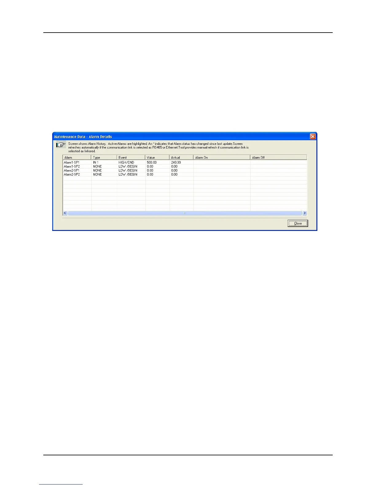
Loop Data – Alarm Details
This screen appears when you click on the Alarm button on the Loop Data Maintenance
Screen and shows the status of each alarm setpoint. NONE in the Type column indicates
that the alarm is disabled. Highlighted alarms are currently active. An asterisk (*)
indicates that the alarm has changed state since the last communications transaction.
For this instrument, the Alarm On and Alarm Off columns will always be blank.
See Section 3.14 for other information about configuring Alarms.
Figure 4-7 Alarm Details Maintenance Screen

Table of Contents

Other manuals for Honeywell UDC2500

Questions and Answers:

Question and Answer IconNeed help?

Do you have a question about the Honeywell UDC2500 and is the answer not in the manual?

Honeywell UDC2500 Specifications

General IconGeneral
TypeUniversal Digital Controller
Alarm RelaysUp to 2 alarm relays
CommunicationRS485 Modbus RTU
MountingPanel Mount
DisplayDual 4-digit LED
Input TypesThermocouple, RTD, mA, V
Control ModesOn/Off, PID
Output TypesRelay, mA, V
Power Supply100-240 VAC, 24V DC
Dimensions96x96x132 mm

Related product manuals