Modbus Read, Write and Override Parameters plus Exception Codes
4/07 UDC2500 Universal Digital Controller Product Manual 217
10.7.12 Display
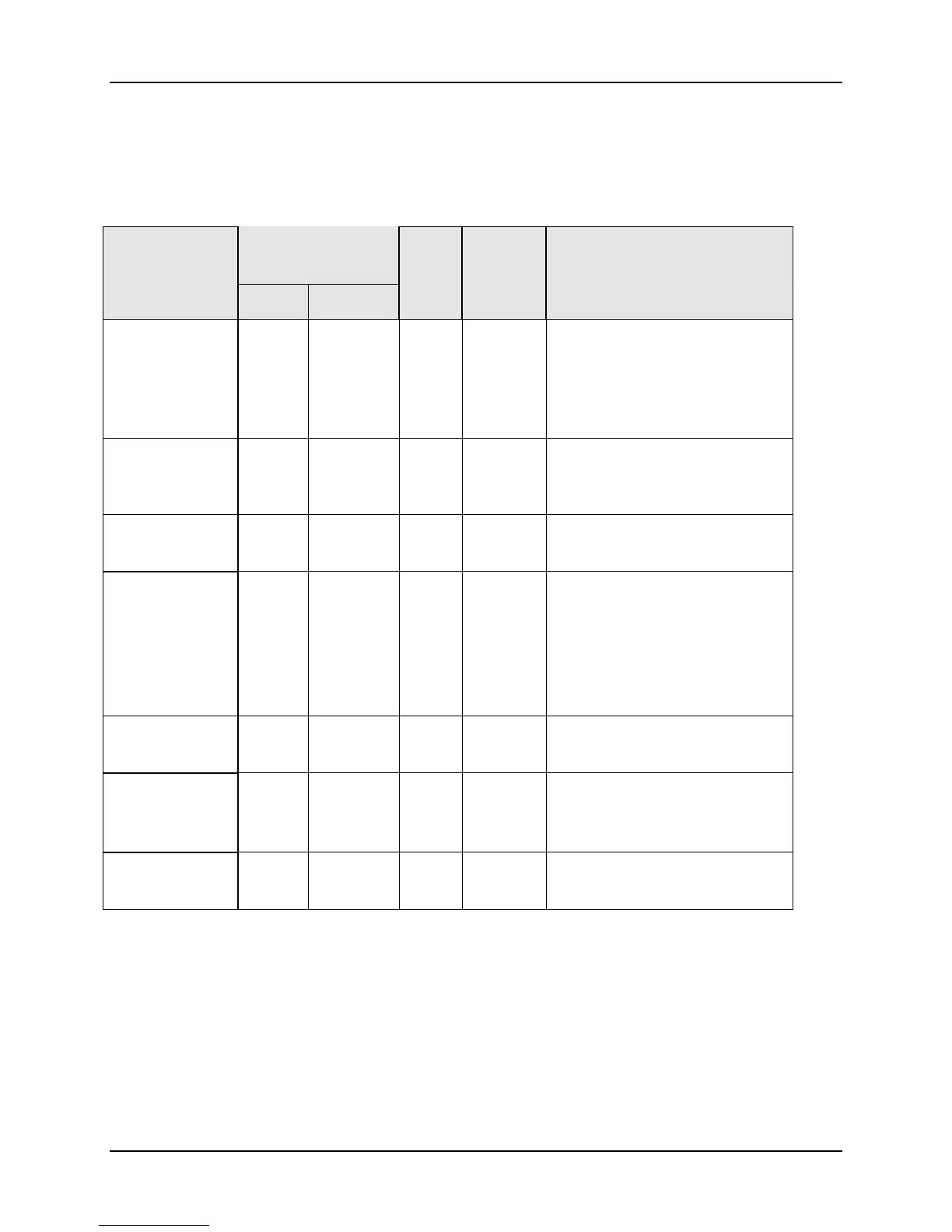
Table 10-20 lists all the register addresses and ranges or selections for the function
parameters in Set-up Group Display.
Table 10-20 Set-up Group – Display
Parameter
Description
Register
Address
Data
Type
Access Data Range or
Enumerated Selection
Hex Decimal
Decimal Point
Location
009B 155 INT R/W
0 = XXXX – Fixed
1 = XXX.X – Floating
decimal point to one
2 = XX.XX – Floating
decimal point to two
Temperature
Units
0081 129 INT R/W
0 = °F
1 = °C
2 = None
Power
Frequency
00A6 166 INT R/W 0 = 60 Hertz
1 = 50 Hertz
Language
(Displays)
00C0 192 INT R/W 0 = English
1 = French
2 = German
3 = Spanish
4 = Italian
5 = Numeric
Lower Display
Enable
00AE 174 INT R/W 0 = Enable
1 = Disable
Lower Display 00AF 175 INT R/W 0 = Setpoint
1 = PRY – PV with Label
2 = PRN – PV witout Label
TC Diagnostics 009f 159 INT R/W 0 = Enable
1 = Disable

 Loading...


