Input Calibration
4/07 UDC2500 Universal Digital Controller Product Manual 147
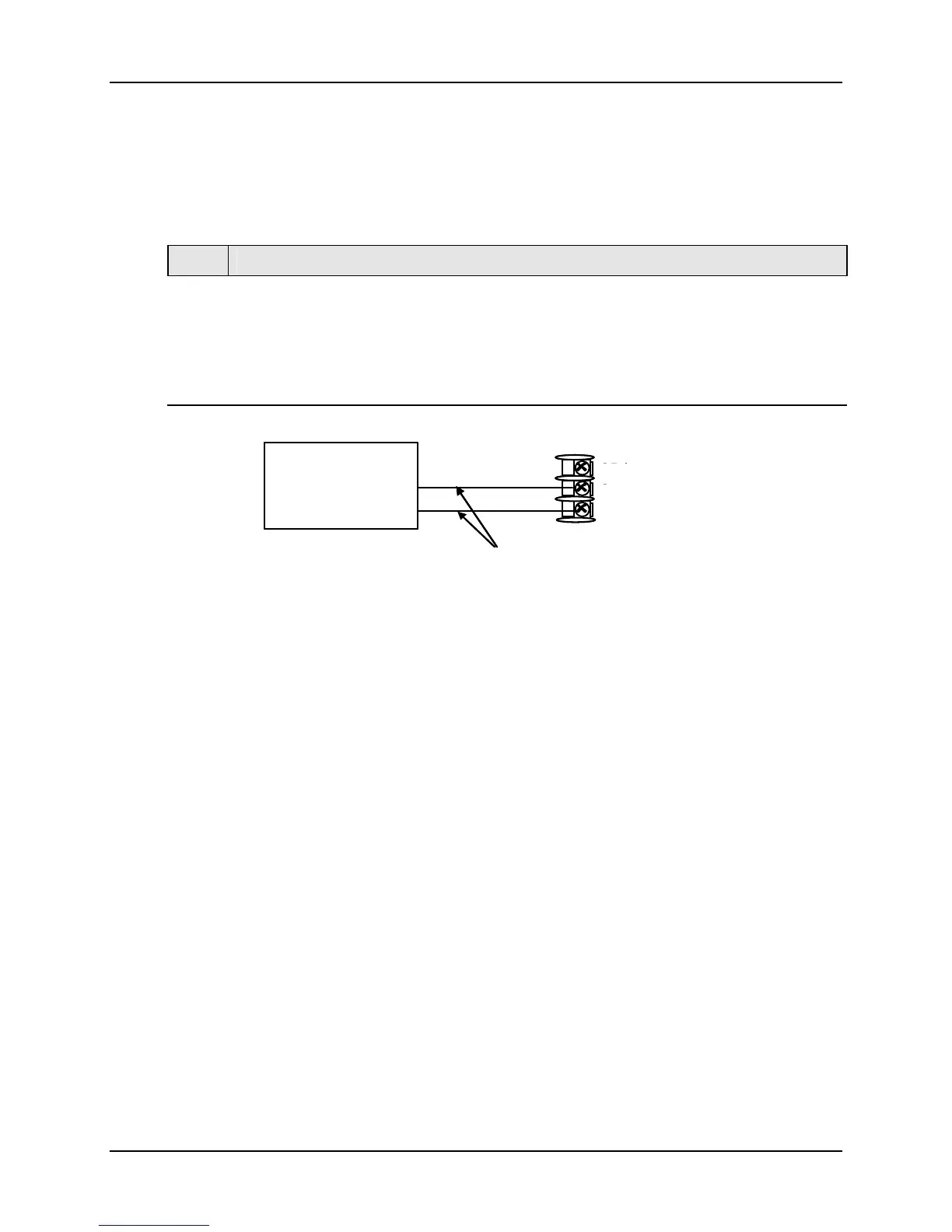
0 to 2 Volts, 0 to 5 Volts, or 1 to 5 Volt Inputs – Input 2
Refer to Figure 5-9 and wire the controller according to the procedure given in Table
5-12.
Table 5-12 Set Up Wiring Procedure for 0 to 2 Volts, 0 to 5 Volts, or 1 to 5
Volts – Input 2
Step Action
1
Connect the copper leads from the calibrator to the Input #2 terminals as shown in
Figure 5-8.
2
Place voltage source at zero before switching on.
3
Do not switch voltage source ON/OFF while connected to the instrument.
Voltage
Source
26 +
27 -
Copper Leads
Equal Length
+
_
25 (no connection)
Voltage
Source
26 +
27 -
Copper Leads
Equal Length
+
_
25 (no connection)
Figure 5-9 Wiring Connections for 0 to 2 Volts, 0 to 5 Volts or 1 to 5 Volts
Input – Input 2
5.7 Input 2 Calibration Procedure
Preliminary Steps
• Apply power and allow the controller to warm up for 30 minutes before you calibrate.
• Please read Subsection
5.6 – before beginning the procedure.
• Make sure you have LOCK set to NONE. See Subsection 3.4 - Tuning Set Up
Group.
Continued next page

 Loading...


