Installation
14 UDC2500 Universal Digital Controller Product Manual 4/07
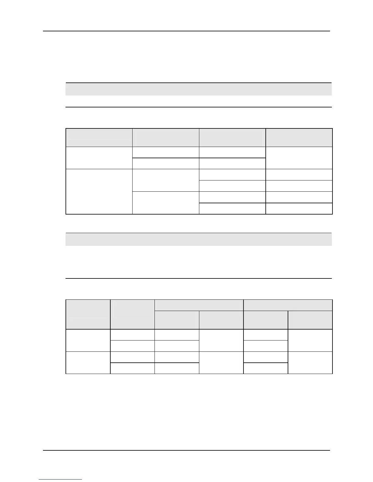
2.4 Control and Alarm Relay Contact Information
Control Relays
ATTENTION
Control relays operate in the standard control mode (that is, energized when output state is on).
Table 2-2 Control Relay Contact Information
Unit Power Control Relay
Wiring
Control Relay
Contact
Output #1 or #2
Indicator Status
N.O. Open
Off
N.C. Closed
Off
Open
Off
N.O.
Closed
On
Closed
Off
On
N.C.
Open
On
Alarm Relays
ATTENTION
Alarm relays are designed to operate in a failsafe mode (that is, de-energized during alarm
sate). This results in alarm actuation when power is OFF or when initially applied, until the unit
completes self diagnostics. If power is lost to the unit, the alarms will de-energize and thus the
alarm contacts will close.
Table 2-3 Alarm Relay Contact Information
Variable NOT in Alarm State Variable in Alarm State Unit
Power
Alarm Relay
Wiring
Relay
Contact
Indicators Relay
Contact
Indicators
N.O. Open Open
Off
N.C. Closed
Off
Closed
Off
N.O. Closed Open
On
N.C. Open
Off
Closed
On

 Loading...


