Input Calibration
148 UDC2500 Universal Digital Controller Product Manual 4/07
Procedure
The calibration procedure for Input #2 is listed in Table 5-13. The numeric codes are also
listed.
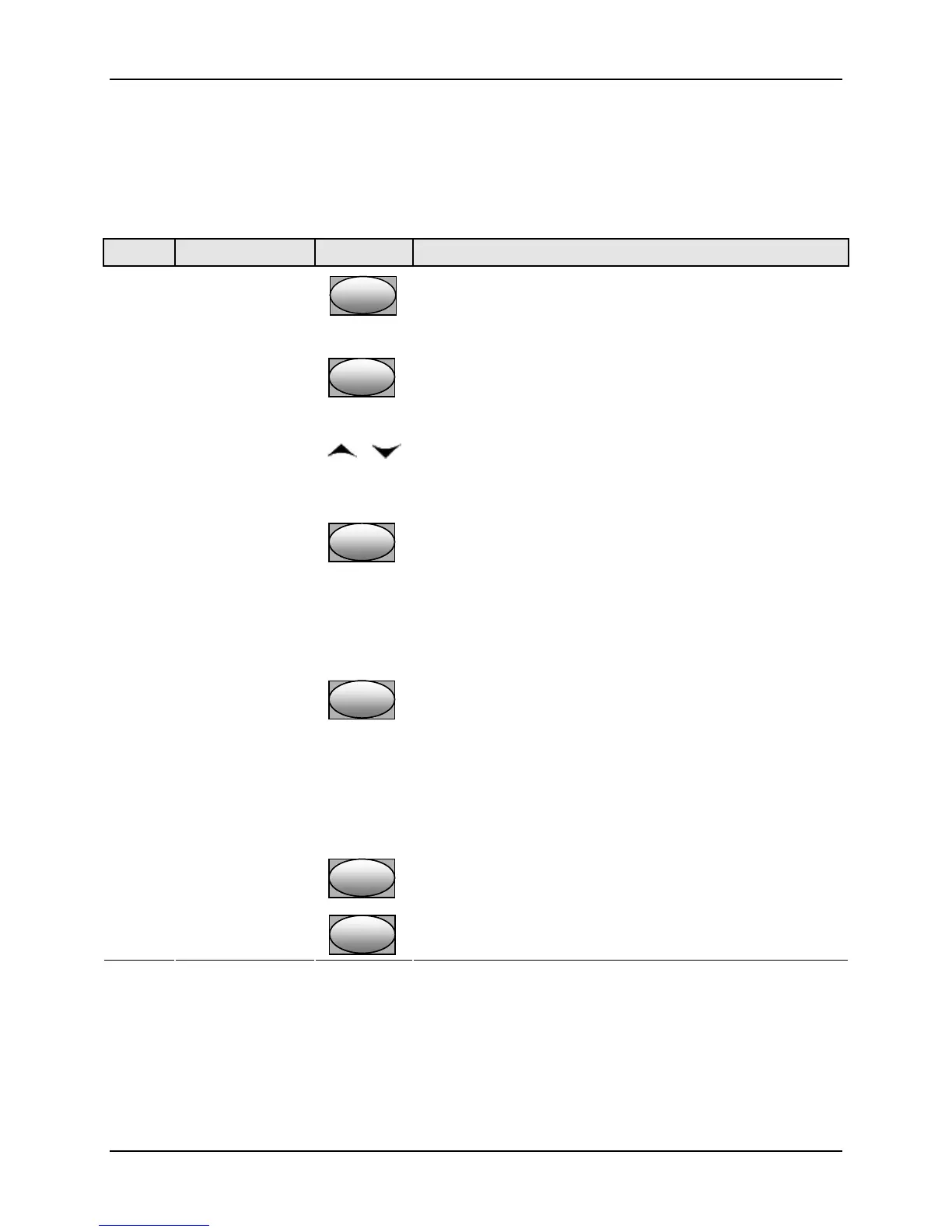
Table 5-13 Input 2 Calibration Procedure (Numeric Code 20000)
Step Operation Press Result
1
Enter Calibration
Mode
SetupSetup
until you see
Upper Display = CAL ( - - - - )
Lower Display = INPUT2 (20000)
FunctionFunctionFunction
You will see:
Upper Display = DIS ( 0 )
Lower Display = CALIN2 (20001)
or
You will see:
Upper Display = BEGN ( 1 )
Lower Display = CALIN2 (20001)
2
Calibrate 0 %
FunctionFunctionFunction
You will see:
Upper Display = APLY ( 2 )
Lower Display = IN2ZRO (20002)
• Adjust your calibration device to an output signal equal
to the 0 % range value for your particular input sensor.
• Wait 15 seconds, then go to the next step.
3
Calibrate 100 %
FunctionFunctionFunction
You will see:
Upper Display = APLY ( 2 )
Lower Display = IN2SPN (20003)
• Adjust your calibration device to an output signal equal
to the 100 % range value for your particular input
sensor.
• Wait 15 seconds, then go to the next step.
4
FunctionFunctionFunction
The controller stores the calibration constants.
Exit the
Calibration Mode
Lower
Display
Lower
Display
Lower
Display
To store the calibration constants and exit the calibration
mode.

 Loading...


