Configuration
4/07 UDC2500 Universal Digital Controller Product Manual 77
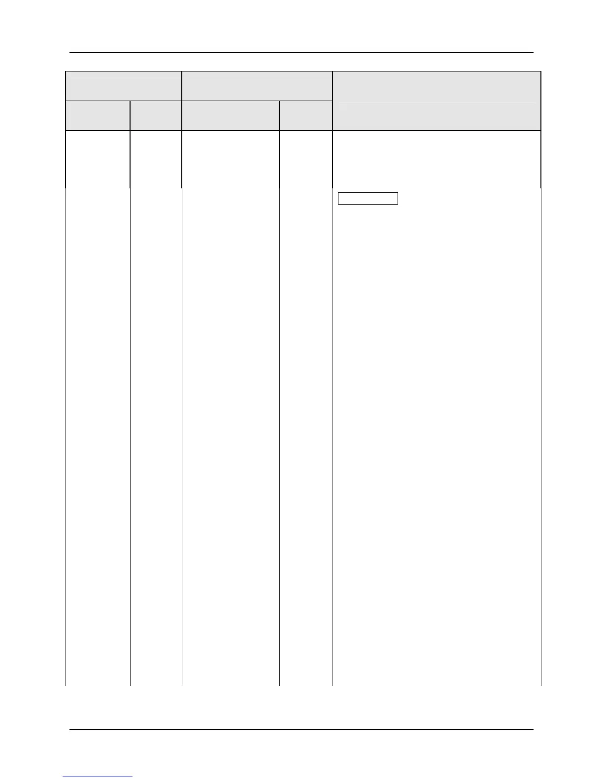
Function Prompt
Lower Display
Selection or Range of Setting
Upper Display
English Numeric
Code
English Numeric
Code
Parameter
Definition
DE 2
TC W
TC F
16
17
18
DEVIATION FROM LSP 2 (NOTE 3)
THERMOCOUPLE WARNING (NOTE 5)
THERMOCOUPLE FAILING (NOTE 6)
ATTENTION
NOTE 1. When the controller is configured
for Three Position Step Control, alarms set
for Output will not function.
NOTE 2. Alarm 1 is not available if the Timer
is enabled because Alarm 1 is dedicated to
Timer output.
NOTE 3. This Deviation Alarm is based upon
deviation from the 2nd Local Setpoint or
Remote SP regardless of whichever SP is
active.
NOTE 4. Loop Break monitors the control
loop to determine if it is working. When
enabled, the control output is checked
against the minimum and maximum output
limit settings. When the output reaches one
of these limits, a timer begins. If the timer
expires and the output has not caused the
PV to move by a pre-determined amount,
then the alarm activates, thus signalling that
the loop is broken. The loop break timer
value must be configured by the operator as
the AxSx VAL entry. This value is in
seconds with a range of 0 to 3600 seconds.
A setting of 0 is equivalent to an
instantaneous loop break when the output
reaches one of its limit values.
The amount of PV Movement required is
determined by the “UNITS” setting in the
Display Setup Group. For the Degrees F
configuration, the PV must move by 3° in the
desired direction in the time allowed. For the
Degrees C configuration, the PV must move
by 2° in the desired direction in the time
allowed. For the “NONE” selection, the PV
must move 1% of the PV range in the time
allowed.
Loop Break alarms do not have a
HIGH/LOW State configuration, they are
always assumed to be a HIGH state alarm.

 Loading...


