318
Summary Count : 1
Static Routing table Status : <Active>
Summary Count : 1
Destination: 120::/64 Protocol : Static
NextHop : 10::100 Preference: 65
Interface : Eth1/2 Cost : 0
Static Routing table Status : <Inactive>
Summary Count : 0
The output shows that Router A communicates with Router B through Ethernet 1/2.
BFD for IPv6 static routes configuration example (indirect next
hop)
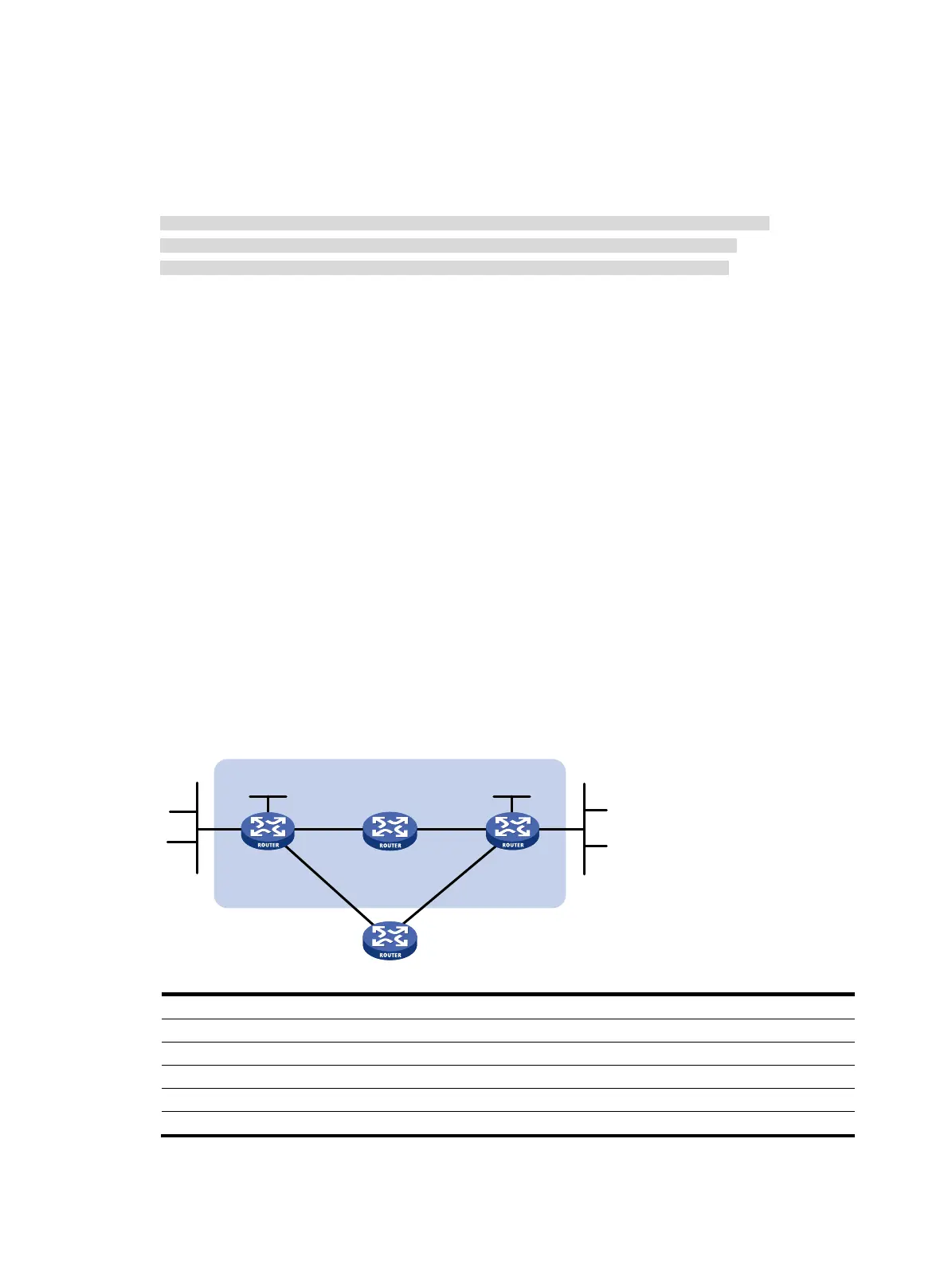
Network requirements
In Figure 82, Router A has a route to interface Loopback 1 (2::9/128) on Router B, with the output
interface being Ethernet 1/1. Router B has a route to interface Loopback 1 (1::9/128) on Router A, with
the output interface being Ethernet 1/1. Router D has a route to 1::9/128, with the output interface being
Ethernet 1/1, and a route to 2::9/128, with the output interface being Ethernet 1/2.
Configure an IPv6 static route to subnet 120::/64 on Router A, and configure an IPv6 static route to
subnet 121::/64 on Router B. Enable BFD for both routes. Configure an IPv6 static route to subnet
120::/64 and an IPv6 static route to subnet 121::/64 on both Router C and Router D. When the link
between Router A and Router B through Router D fails, BFD can detect the failure immediately and Router
A and Router B can communicate through Router C.
Figure 82 Network diagram
Device Interface IPv6 address
Device
Interface
IPv6 address
Router A Eth1/1 12::1/64 Router B Eth1/1 11::2/64
Eth1/2 10::102/64
Eth1/2
13::1
64
Loop1 1::9/128
Loop1
2::9/128
Router C Eth1/1 10::100/64 Router D Eth1/1 12::2/64
Eth1/2 13::2/64
Eth1/2
11::1/64
Router A Router B
Eth1/1 Eth1/1
Router C
BFD
Eth1/1
Eth1
/2
Eth
1/2
Eth1/2
121::/64 120::/64
Router D
Eth1/1 Eth1/2
Loop1
1::9/128
Loop1
2::9/128

 Loading...


