16
BFD for static routes configuration example (indirect next hop)
Network requirements
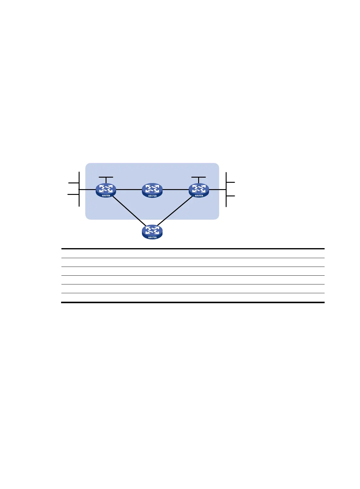
In Figure 4, Router A has a route to interface Loopback 1 (2.2.2.9/32) on Router B, with the output
interface Ethernet 1/1. Router B has a route to interface Loopback 1 (1.1.1.9/32) on Router A, with the
output interface Ethernet 1/1. Router D has a route to 1.1.1.9/32, with the output interface Ethernet 1/1,
and a route to 2.2.2.9/32, with the output interface Ethernet 1/2.
Configure a static route to subnet 120.1.1.0/24 on Router A, and configure a static route to subnet
121.1.1.0 / 24 o n Ro u t e r B . E n a b l e B F D fo r b o t h r o u t e s . C o n f i g u re a s t a t i c ro u t e t o s u b n e t 12 0 .1.1.0 / 24 a n d
a static route to subnet 121.1.1.0/24 on both Router C and Router D. When the link between Router A and
Router B through Router D fails, BFD can detect the failure immediately and inform Router A and Router
B to communicate through Router C.
Figure 4 Network diagram
Device Interface IP address Device Interface IP address
Router A Eth1/1 12.1.1.1/24
Router B
Eth1/1
11.1.1.2/24
Eth1/2 10.1.1.102/24
Eth1/2
13.1.1.2/24
Loop1 1.1.1.9/32 Loop1 2.2.2.9/32
Router C Eth1/1 10.1.1.100/24
Router D
Eth1/1
12.1.1.2/24
Eth1/2 13.1.1.2/24
Eth1/2
11.1.1.2/24
Configuration procedure
1. Configure IP addresses for interfaces. (Details not shown.)
2. Configure static routes and BFD:
# Configure static routes on Router A and enable BFD control mode for the static route that
traverses Router D.
<RouterA> system-view
[RouterA] bfd multi-hop min-transmit-interval 500
[RouterA] bfd multi-hop min-receive-interval 500
[RouterA] bfd multi-hop detect-multiplier 9
[RouterA] ip route-static 120.1.1.0 24 2.2.2.9 bfd control-packet bfd-source 1.1.1.9
[RouterA] ip route-static 120.1.1.0 24 ethernet 1/2 10.1.1.100 preference 65
[RouterA] quit
# Configure static routes on Router B and enable BFD control mode for the static route that
traverses Router D.
<RouterB> system-view
Router A Router B
Eth1/1 Eth1/1
Router C
BFD
Eth1/1
Eth1/2
Eth1/
2
Eth1/2
121.1.1.0/24 120.1.1.0/24
Router D
Eth1/1 Eth1/2
Loop1
1.1.1.9/32
Loop1
2.2.2.9/32

 Loading...


