118
OrigTblID: 0x0 OrigVrf: default-vrf
TableID: 0x2 OrigAs: 0
NBRID: 0x26000002 LastAs: 0
AttrID: 0xffffffff Neighbor: 0.0.0.0
Flags: 0x1008c OrigNextHop: 10.1.1.100
Label: NULL RealNextHop: 10.1.1.100
BkLabel: NULL BkNextHop: N/A
Tunnel ID: Invalid Interface: Ethernet1/2
BkTunnel ID: Invalid BkInterface: N/A
The output shows that Router A communicates with Router B through Ethernet 1/2.
OSPF FRR configuration example
Network requirements
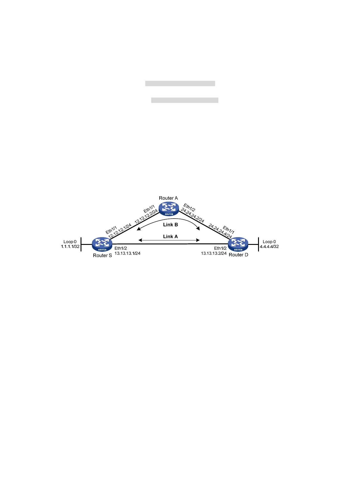
As shown in Figure 31, Router S, Router A, and Router D reside in the same OSPF domain. Configure
OSPF FRR so that when Link A fails, traffic is immediately switched to Link B.
Figure 31 Network diagram
Configuration procedure
1. Configure IP addresses and subnet masks for interfaces on the routers. (Details not shown.)
2. Configure OSPF on the routers to make sure Router S, Router A, and Router D can communicate
with each other at the network layer. (Details not shown.)
3. Configure OSPF FRR:
You can enable OSPF FRR to either calculate a backup next hop by using the LFA algorithm, or
specify a backup next hop by using a routing policy.
{ (Method 1.) Enable OSPF FRR to calculate a backup next hop by using the LFA algorithm:
# Configure Router S.
<RouterS> system-view
[RouterS] bfd echo-source-ip 1.1.1.1
[RouterS] ospf 1
[RouterS-ospf-1] fast-reroute lfa
[RouterS-ospf-1] quit
# Configure Router D.
<RouterD> system-view
[RouterD] bfd echo-source-ip 4.4.4.4
[RouterD] ospf 1
[RouterD-ospf-1] fast-reroute lfa

 Loading...


