40
2.1.1.0/24 1.1.1.1 1 0 RAOF 19
3.1.1.0/24 1.1.1.1 1 0 RAOF 19
# Display the RIP routing table on Router B.
[RouterB] display rip 1 route
Route Flags: R - RIP
A - Aging, S - Suppressed, G - Garbage-collect
O - Optimal, F - Flush to RIB
----------------------------------------------------------------------------
Peer 1.1.1.1 on Ethernet1/1
Destination/Mask Nexthop Cost Tag Flags Sec
2.1.1.0/24 1.1.1.1 1 0 RAOF 19
Configuring RIP route redistribution
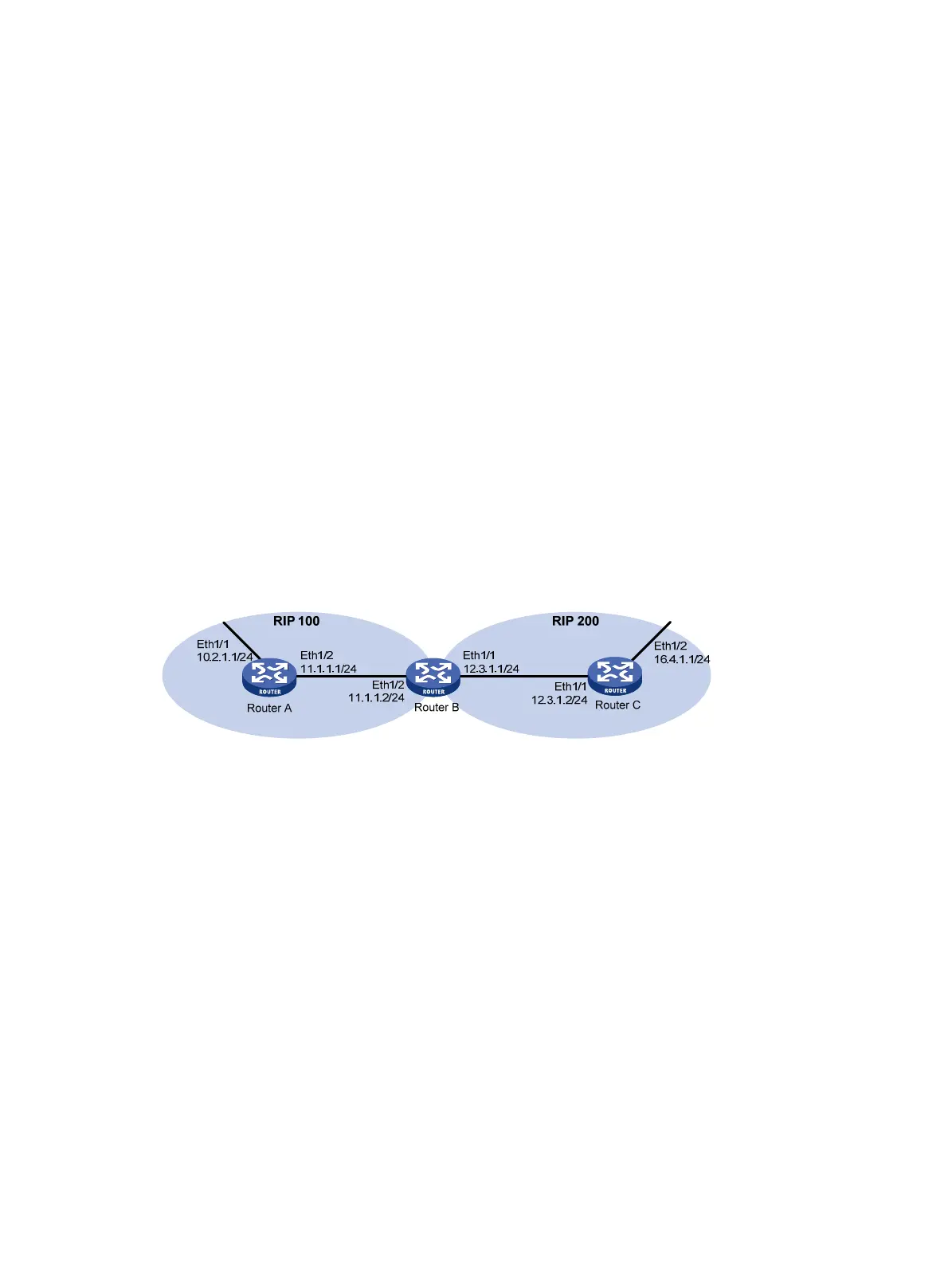
Network requirements
As shown in Figure 8, Router B communicates with Router A through RIP 100 and with Router C through
RIP 200.
Configure RIP 200 to redistribute direct routes and routes from RIP 100 on Router B so Router C can learn
routes destined for 10.2.1.0/24 and 11.1.1.0 / 24 . R o u t e r A c a n n o t l e a r n ro u t e s d e s t i n e d f o r 12.3.1. 0 / 24
and 16.4.1.0/24.
Figure 8 Network diagram
Configuration procedure
1. Configure IP addresses for interfaces. (Details not shown.)
2. Configure basic RIP:
# Enable RIP 100, and configure RIPv2 on Router A.
<RouterA> system-view
[RouterA] rip 100
[RouterA-rip-100] network 10.0.0.0
[RouterA-rip-100] network 11.0.0.0
[RouterA-rip-100] version 2
[RouterA-rip-100] undo summary
[RouterA-rip-100] quit
# Enable RIP 100 and RIP 200, and configure RIPv2 on Router B.
<RouterB> system-view
[RouterB] rip 100
[RouterB-rip-100] network 11.0.0.0
[RouterB-rip-100] version 2
[RouterB-rip-100] undo summary

 Loading...


