316
BFD for IPv6 static routes configuration example (direct next
hop)
Network requirements
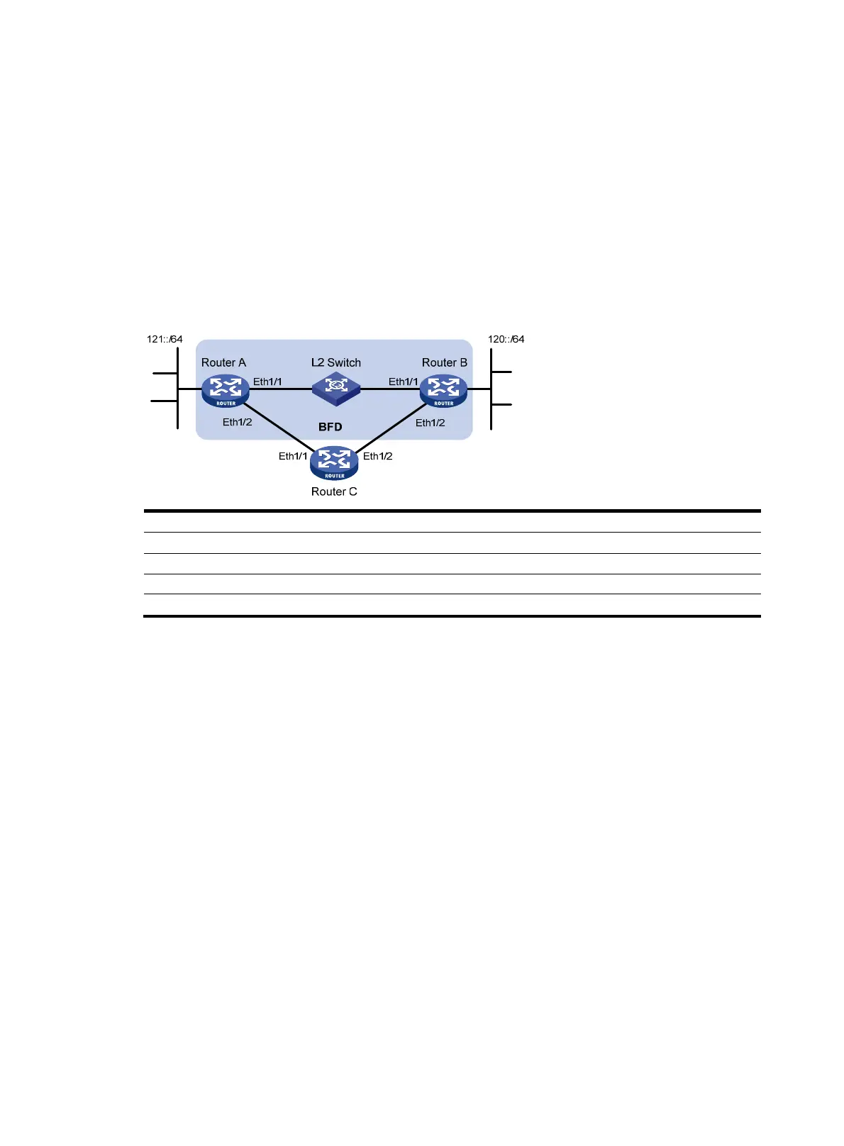
In Figure 81, configure an IPv6 static route to subnet 120::/64 on Router A, and configure an IPv6 static
route to subnet 121::/64 on Router B. Enable BFD for both routes. Configure an IPv6 static route to subnet
120::/64 and an IPv6 static route to subnet 121::/64 on Router C. When the link between Router A and
Router B through the Layer 2 switch fails, BFD can detect the failure immediately and inform Router A and
Router B to communicate through Router C.
Figure 81 Network diagram
Device Interface IPv6 address
Device
Interface
IPv6 address
Router A Eth
1/1 12::1/64
Router B
Eth
1/1
12::2/64
Eth 1/2 10::102/64 Eth 1/2 13::1/64
Router C Eth
1/1 10::100/64
Eth
1/2 13::2/64
Configuration procedure
1. Configure IPv6 addresses for interfaces. (Details not shown.)
2. Configure IPv6 static routes and BFD:
# Configure IPv6 static routes on Router A, and enable BFD control mode for the IPv6 static route
that traverses Ethernet 1/1.
<RouterA> system-view
[RouterA] interface ethernet 1/1
[RouterA-Ethernet1/1] bfd min-transmit-interval 500
[RouterA-Ethernet1/1] bfd min-receive-interval 500
[RouterA-Ethernet1/1] bfd detect-multiplier 9
[RouterA-Ethernet1/1] quit
[RouterA] ipv6 route-static 120:: 64 ethernet 1/1 FE80::2E0:FCFF:FE58:123E bfd
control-packet
[RouterA] ipv6 route-static 120:: 64 10::100 preference 65
[RouterA] quit
# Configure IPv6 static routes on Router B, and enable BFD control mode for the IPv6 static route
that traverses the Layer 2 switch.
<RouterB> system-view
[RouterB] interface ethernet 1/1
[RouterB-Ethernet1/1] bfd min-transmit-interval 500

 Loading...


