55
# Display RIP routes destined for 100.1.1.0/24 on Router A when the link between Router B and
Router C fails.
<RouterA> display ip routing-table 100.1.1.0 verbose
Summary Count : 1
Destination: 100.1.1.0/24
Protocol: RIP Process ID: 2
SubProtID: 0x1 Age: 00h10m35s
Cost: 2 Preference: 100
Tag: 0 State: Active Adv
OrigTblID: 0x0 OrigVrf: default-vrf
TableID: 0x2 OrigAs: 0
NBRID: 0x12000003 LastAs: 0
AttrID: 0xffffffff Neighbor: 192.168.3.2
Flags: 0x1008c OrigNextHop: 192.168.3.2
Label: NULL RealNextHop: 192.168.3.2
BkLabel: NULL BkNextHop: N/A
Tunnel ID: Invalid Interface: Ethernet1/2
BkTunnel ID: Invalid BkInterface: N/A
Configuring RIP FRR
Network requirements
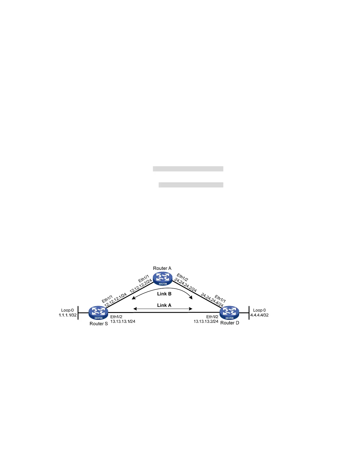
As shown in Figure 14, Router S, Router A, and Router D run RIPv2. Configure RIP FRR so that when Link
A becomes unidirectional, traffic can be switched to Link B immediately.
Figure 14 Network diagram
Configuration procedure
1. Configure IP addresses and subnet masks for interfaces on the routers. (Details not shown.)
2. Configure RIPv2 on the routers to make sure Router A, Router D, and Router S can communicate
with each other at the network layer. (Details not shown.)
3. Configure RIP FRR:
# Configure Router S.
<RouterS> system-view
[RouterS] bfd echo-source-ip 1.1.1.1
[RouterS] ip prefix-list abc index 10 permit 4.4.4.4 32
[RouterS] route-policy frr permit node 10

 Loading...


