171
Flags: 0x1008c OrigNextHop: 192.168.0.100
Label: NULL RealNextHop: 192.168.0.100
BkLabel: NULL BkNextHop: N/A
Tunnel ID: Invalid Interface: Ethernet1/1
BkTunnel ID: Invalid BkInterface: N/A
The output shows that Router A and Router B communicate through Ethernet 1/1. Then the link over
Ethernet 1/1 fails.
# Display routes destined for 120.1.1.0/24 on Router A.
<RouterA> display ip routing-table 120.1.1.0 verbose
Summary Count : 1
Destination: 120.1.1.0/24
Protocol: ISIS Process ID: 1
SubProtID: 0x1 Age: 04h20m37s
Cost: 20 Preference: 10
Tag: 0 State: Active Adv
OrigTblID: 0x0 OrigVrf: default-vrf
TableID: 0x2 OrigAs: 0
NBRID: 0x26000002 LastAs: 0
AttrID: 0xffffffff Neighbor: 0.0.0.0
Flags: 0x1008c OrigNextHop: 10.1.1.100
Label: NULL RealNextHop: 10.1.1.100
BkLabel: NULL BkNextHop: N/A
Tunnel ID: Invalid Interface: Ethernet1/2
BkTunnel ID: Invalid BkInterface: N/A
The output shows that Router A and Router B communicate through Ethernet 1/2.
IS-IS FRR configuration example
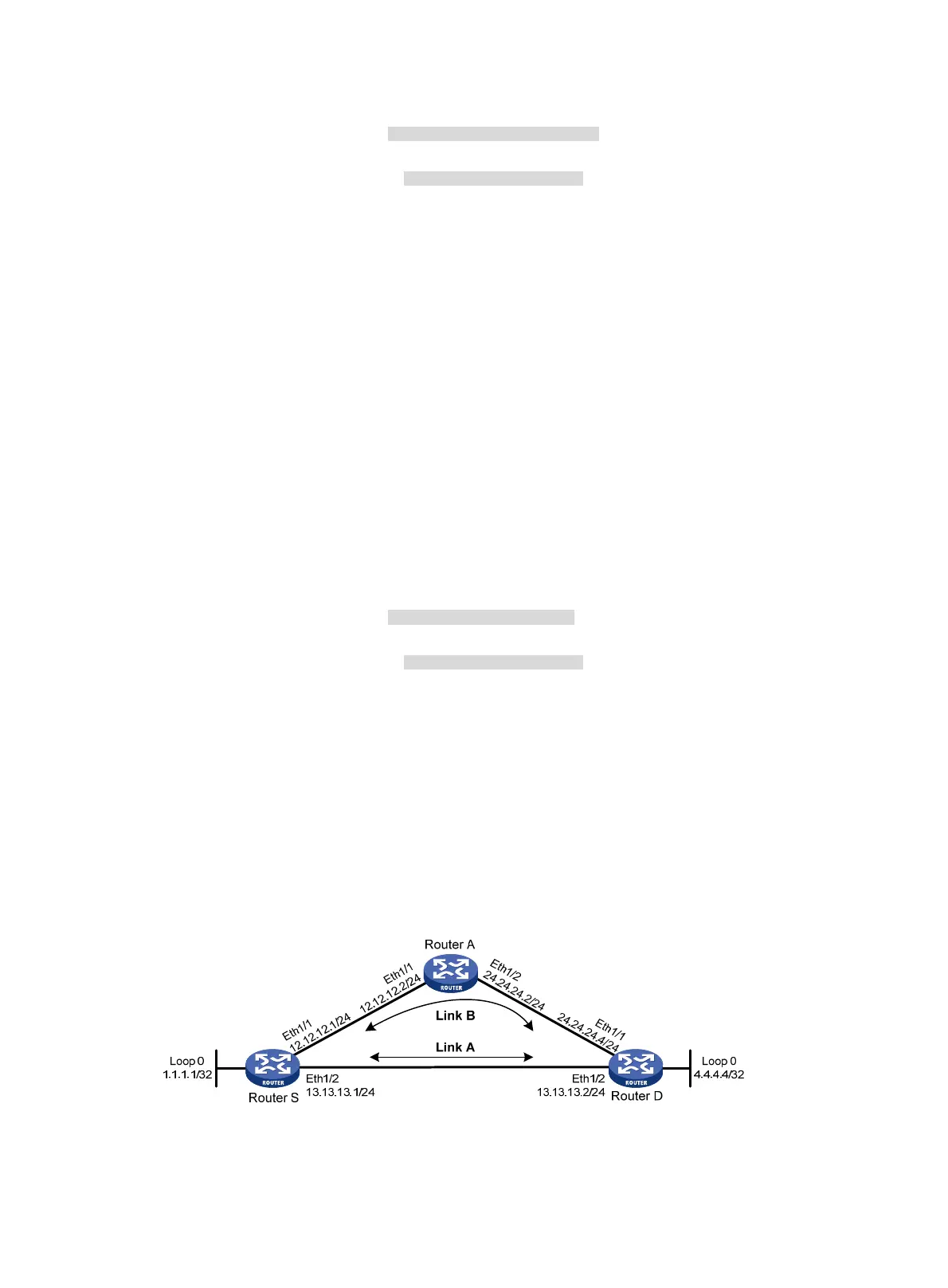
Network requirements
As shown in Figure 46 ,Router S, Router A, and Router D reside in the same IS-IS routing domain. Run
IS-IS on all the routers to interconnect them with each other. Configure IS-IS FRR so that when Link A fails,
traffic can be switched to Link B immediately.
Figure 46 Network diagram

 Loading...


