115
%Oct 21 15:29:29:902 2011 RouterA OSPF/5/OSPF_NBR_CHG: -MDC=1; OSPF 100 Neighbor
192.1.1.2(Ethernet1/1) from Loading to Full.
*Oct 21 15:29:29:902 2011 RouterA OSPF/7/DEBUG: -MDC=1;
OSPF 100 deleted OOB Progress timer for neighbor 192.1.1.2.
%Oct 21 15:29:30:897 2011 RouterA OSPF/5/OSPF_NBR_CHG: -MDC=1; OSPF 100 Neighbor
192.1.1.3(Ethernet1/1) from Loading to Full.
*Oct 21 15:29:30:897 2011 RouterA OSPF/7/DEBUG: -MDC=1;
OSPF 100 deleted OOB Progress timer for neighbor 192.1.1.3.
*Oct 21 15:29:30:911 2011 RouterA OSPF/7/DEBUG: -MDC=1;
OSPF GR: Process 100 Exit Restart,Reason : DR or BDR change,for neighbor : 192.1.1.3.
*Oct 21 15:29:30:911 2011 RouterA OSPF/7/DEBUG: -MDC=1;
OSPF 100 deleted GR Interval timer.
*Oct 21 15:29:30:912 2011 RouterA OSPF/7/DEBUG: -MDC=1;
OSPF 100 deleted GR wait timer.
%Oct 21 15:29:30:920 2011 RouterA OSPF/5/OSPF_NBR_CHG: -MDC=1; OSPF 100 Neighbor
192.1.1.2(Ethernet1/1) from Full to Down.
%Oct 21 15:29:30:921 2011 RouterA OSPF/5/OSPF_NBR_CHG: -MDC=1; OSPF 100 Neighbor
192.1.1.3(Ethernet1/1) from Full to Down.
%Oct 21 15:29:33:815 2011 RouterA OSPF/5/OSPF_NBR_CHG: -MDC=1; OSPF 100 Neighbor
192.1.1.3(Ethernet1/1) from Loading to Full.
%Oct 21 15:29:35:578 2011 RouterA OSPF/5/OSPF_NBR_CHG: -MDC=1; OSPF 100 Neighbor
192.1.1.2(Ethernet1/1) from Loading to Full.
The output shows that Router A completes GR.
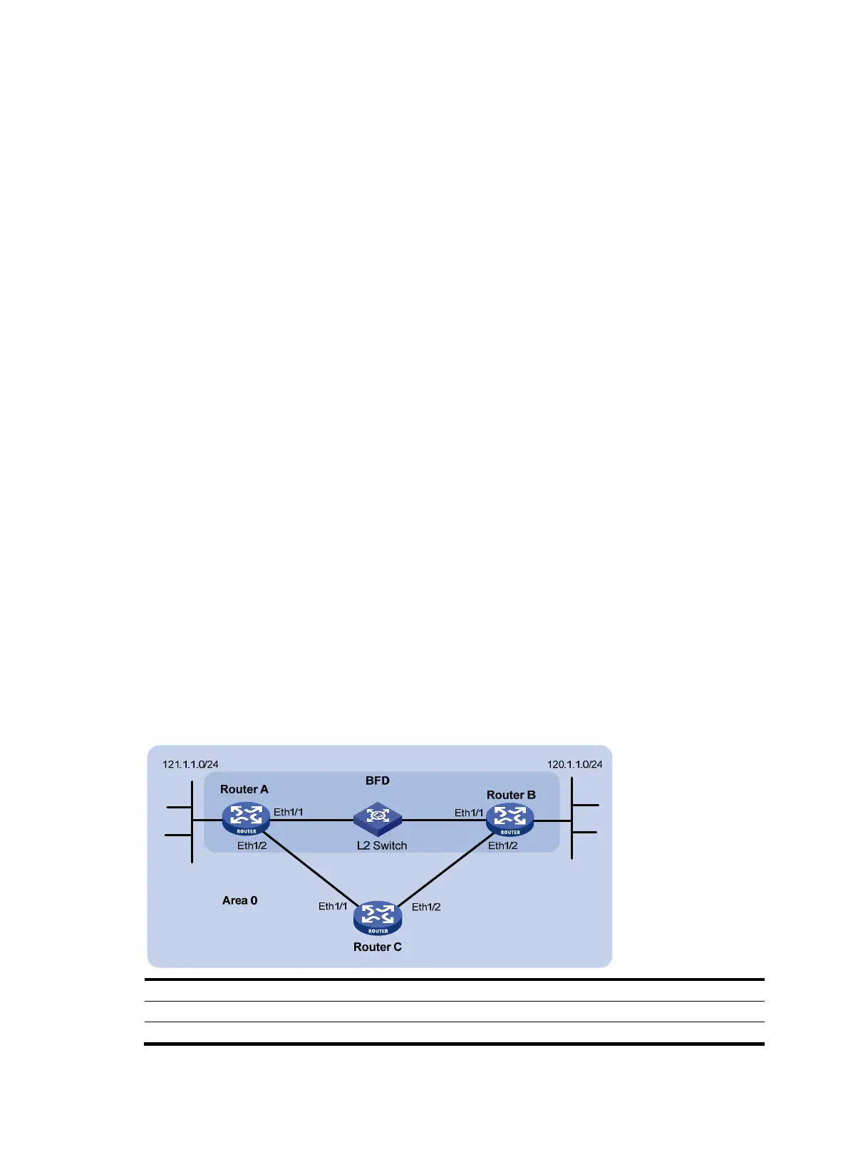
BFD for OSPF configuration example
Network requirements
As shown in Figure 30, run OSPF on Router A, Router B, and Router C so that they can reach each other
at the network layer. When the link over which Router A and Router B communicate through a Layer 2
switch fails, BFD can quickly detect the failure and notify OSPF of the failure. Router A and Router B then
communicate through Router C.
Figure 30 Network diagram
Device Interface IP address
Device
Interface
IP address
Router A Eth 1/1 192.168.0.102/24
Router B Eth 1/1 192.168.0.100/24
Eth
1/2 10.1.1.102/24
Eth
1/2
13.1.1.1/24

 Loading...


