365
[RouterC] ospfv3 1
[RouterC-ospfv3-1] router-id 3.3.3.3
[RouterC-ospfv3-1] quit
[RouterC] interface ethernet 1/1
[RouterC-Ethernet1/1] ospfv3 1 area 1
[RouterC-Ethernet1/1] quit
Verifying the configuration
After all routers function correctly, perform an active/standby switchover on Router A to trigger an
OSPFv3 GR operation.
Configuring BFD for OSPFv3
Network requirements
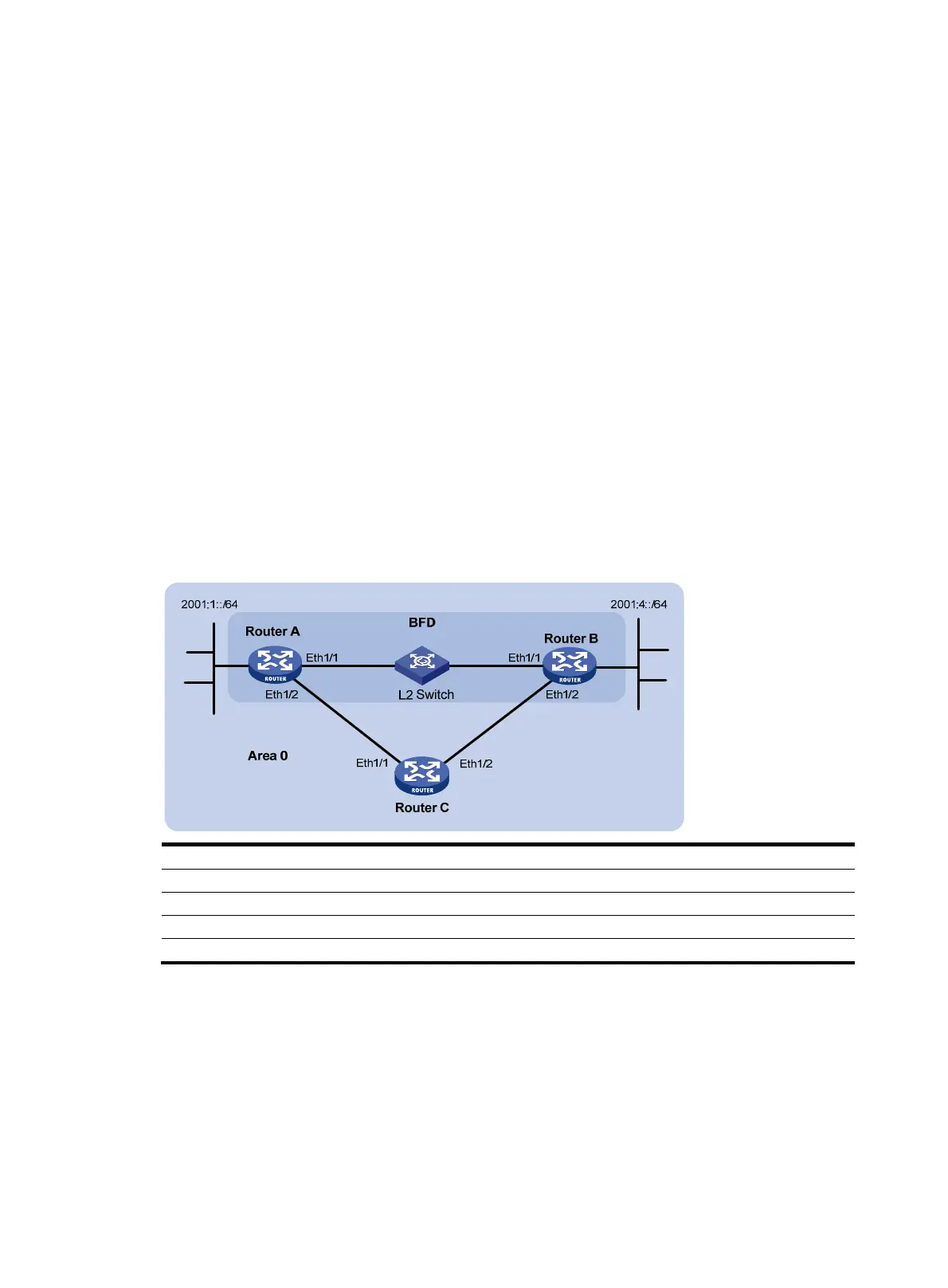
As shown in Figure 90:
• Configure OSPFv3 on Router A, Router B and Router C and configure BFD over the link Router
A<—>L2 Switch<—>Router B.
• After the link Router A<—>L2 Switch<—>Router B fails, BFD can quickly detect the failure and
notify OSPFv3 of the failure. Then Router A and Router B communicate through Router C.
Figure 90 Network diagram
Device Interface IPv6 address Device Interface IPv6 address
Router A Eth1/1 2001::1/64
Router B
Eth1/1
2001::2/64
Eth1/2 2001:2::1/64
Eth1/2
2001:3::2/64
Router C Eth1/1 2001:2::2/64
Eth1/2 2001:3::1/64
Configuration procedure
1. Configure IP addresses for interfaces. (Details not shown.)
2. Configure basic OSPFv3:
# Enable OSPFv3 and set the router ID to 1.1.1.1 on Router A.
<RouterA> system-view
[RouterA] ospfv3 1
[RouterA-ospfv3-1] router-id 1.1.1.1
[RouterA-ospfv3-1] quit

 Loading...


