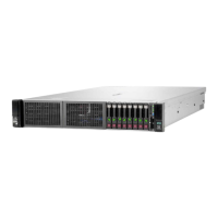
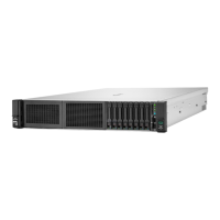
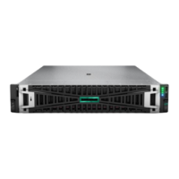
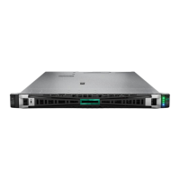
6. Place the server on a flat, level work surface.
7. Remove the access panel.
8. If the server is in the rear 4 LFF drive configuration, remove the rear 4 LFF drive cage.
9. Do one of the following:
a. If replacing the adapter on Slot 21, remove the primary riser cage.
b. If replacing the adapter on Slot 22, remove the secondary riser cage.
10. Remove the OCP NIC 3.0 adapter:
a. Rotate the locking pin to the open (vertical) position (callout 1).
b. Slide the adapter out of the bay (callout 2).
ResultsResults
To replace the component, reverse the removal procedure.
Removing and replacing the chassis intrusion detection switchRemoving and replacing the chassis intrusion detection switch
ProcedureProcedure
1. Power down the server.
2. If installed, open the cable management arm.
 Loading...
