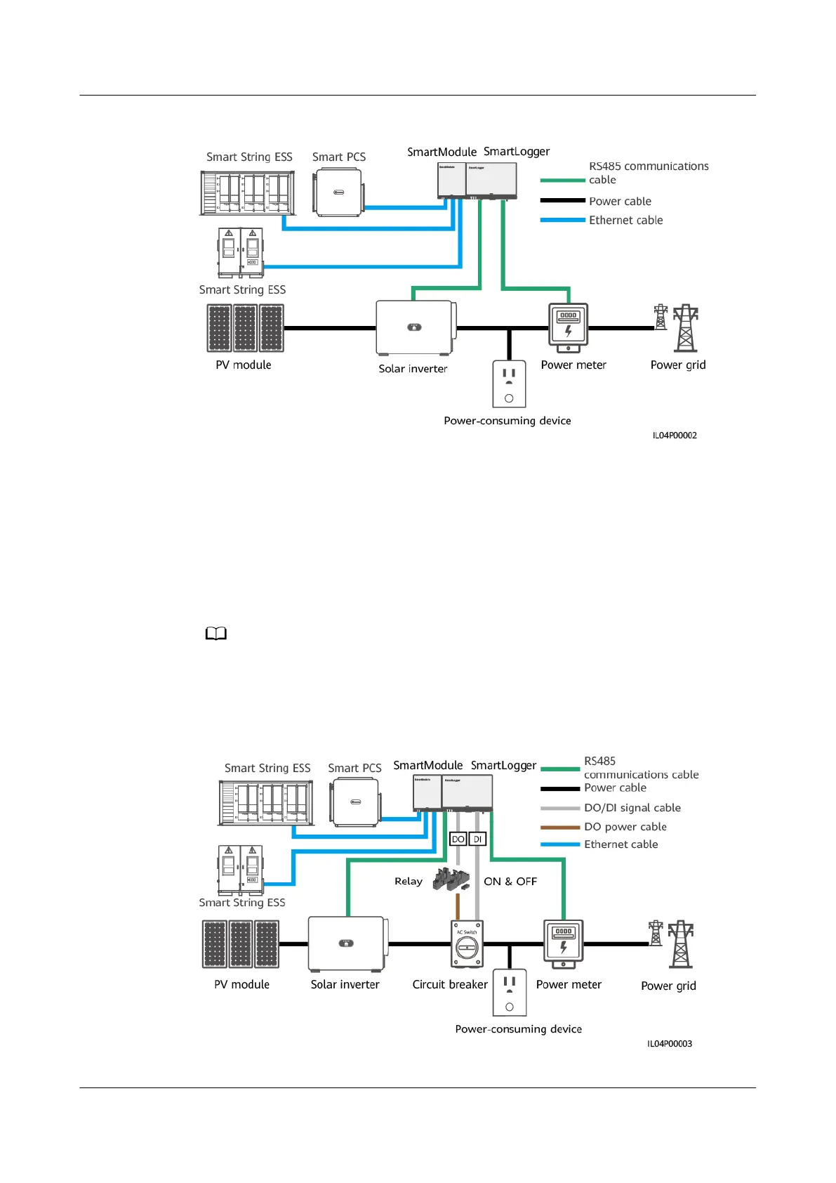
Figure 6-74 Network diagram (without a circuit breaker)
● Scenario with a circuit breaker: When the reverse current feeding into the
power grid cannot be eliminated by sending a command from the
SmartLogger to adjust the inverter/Smart PCS output power, and the
Maximum protection time is exceeded, the SmartLogger drives the relay to
switch
o the circuit breaker by controlling the DO port. When the DI port
detects that the circuit breaker is open, the DO port and relay on the
SmartLogger will be switched
o, and the SmartLogger will restore to the
initial state.
Connect the DO ports in series to the 12 V power supply loop of the relay coils. You are
advised to use the 12 V power output port on the SmartLogger to power the relay coils. You
can also prepare a 12 V power supply.
Figure 6-75 Network diagram (with a circuit breaker)
SmartLogger3000
User Manual 6 WebUI Operations
Issue 10 (2022-08-20) Copyright © Huawei Technologies Co., Ltd. 221