SYSTEM CONFIGURATION
940043-002 INTEGRATED ENTERPRISE NETWORK 5-7
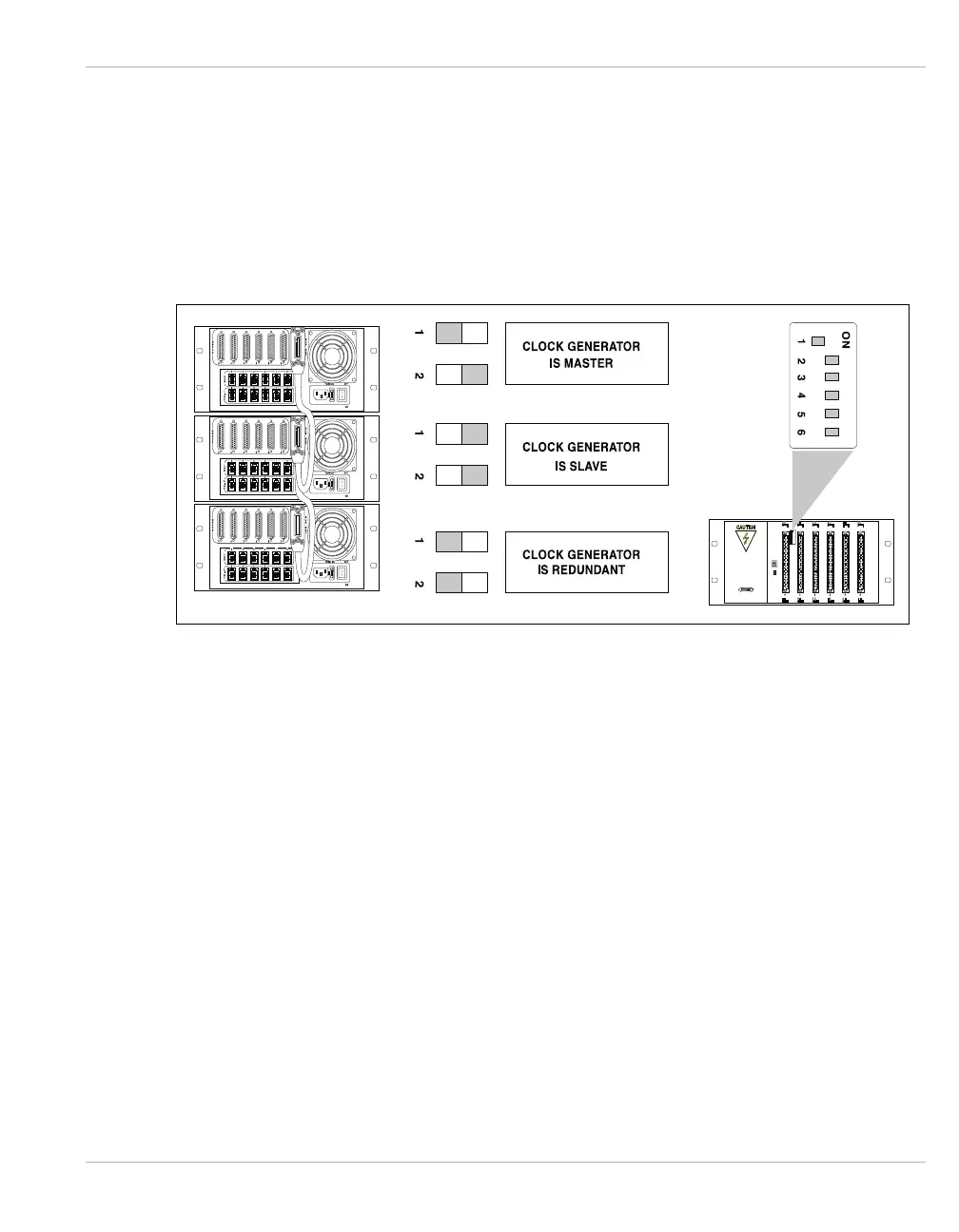
DIP Switch Settings
The Hypercom IEN 3000 chassis may be bus connected using a Hypercom Type B cable, up
to three chassis. In a two chassis IEN 3000 configuration, one chassis must be set to Master
Clock (default factory settings), and the other must be set to Redundant Clock. If the Master
Clock fails, the redundant clock takes over. Figure 5-4 illustrates the DIP switch settings for
the IEN 3000 chassis.
Figure 5-4 IEN 3000 DIP Switch Settings
Note: The Master and Redundant chassis are end points of the expanded bus and require bus
terminators attached to the Type B cables. Refer to CHAPTER 4, Type B for more information
about the Hypercom Type B cable and terminator.