CHAPTER 3
3-10 IEN HARDWARE REFERENCE 940043-002
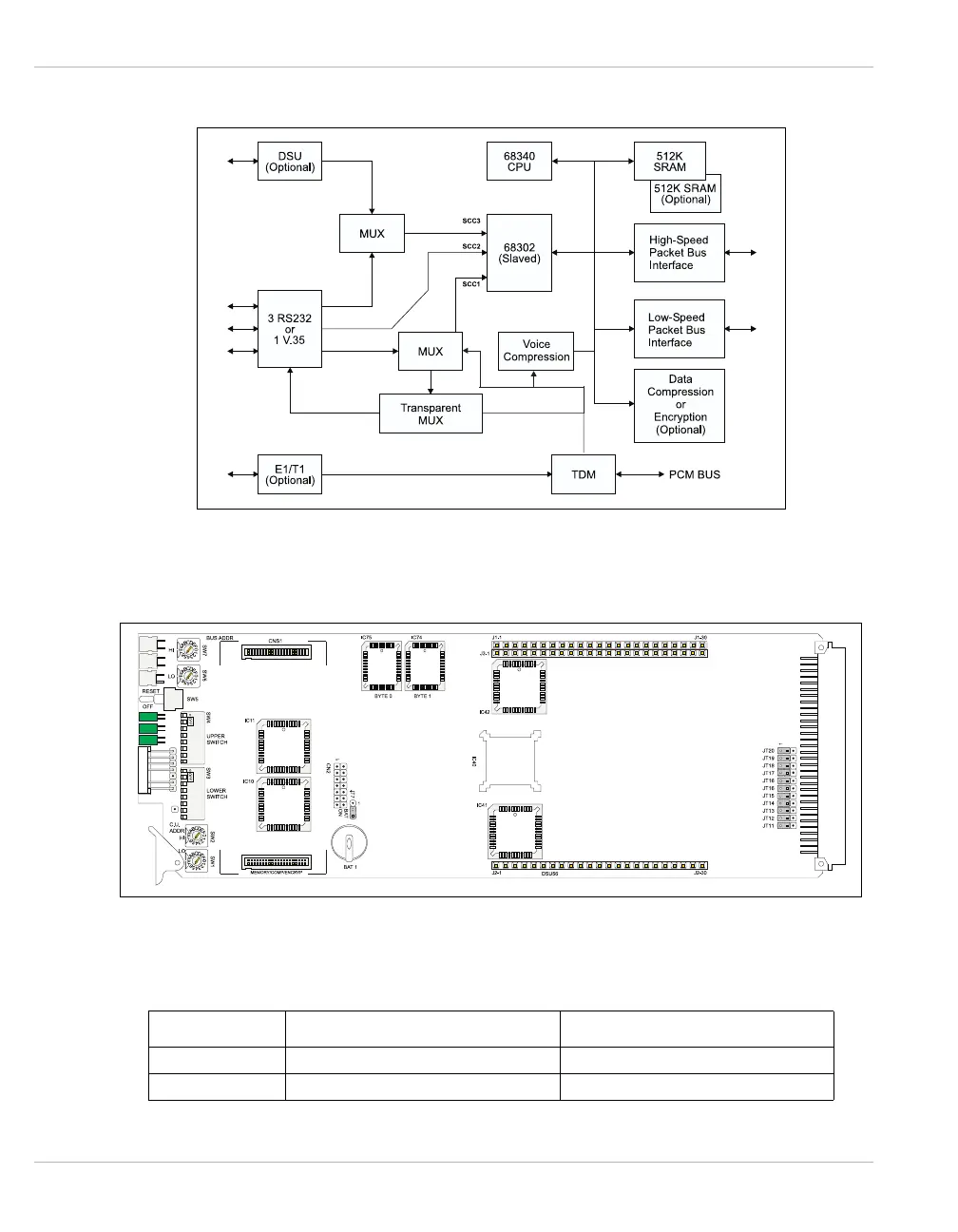
Figure 3-8 illustrates the block diagram for the CID61 port processor.
Figure 3-8 CID61 Block Diagram
Figure 3-9 illustrates the jumper locations for the CID61 port processor.
Figure 3-9 CID61 Jumper Locations
Table 3-2 lists the jumper definitions for the CID61 port processor.
Table 3-2 CID61 Jumper Definitions
JUMPER DESCRIPTION FACTORY SETTING
JT7 Battery On/Off Battery On: Pins 2 & 3 connected.
JT11-JT20 V.35/RS232 Left = V.35/Right = RS232.