192 Powermax30 AIR Service Manual 808850
7 – Torch Component Replacement
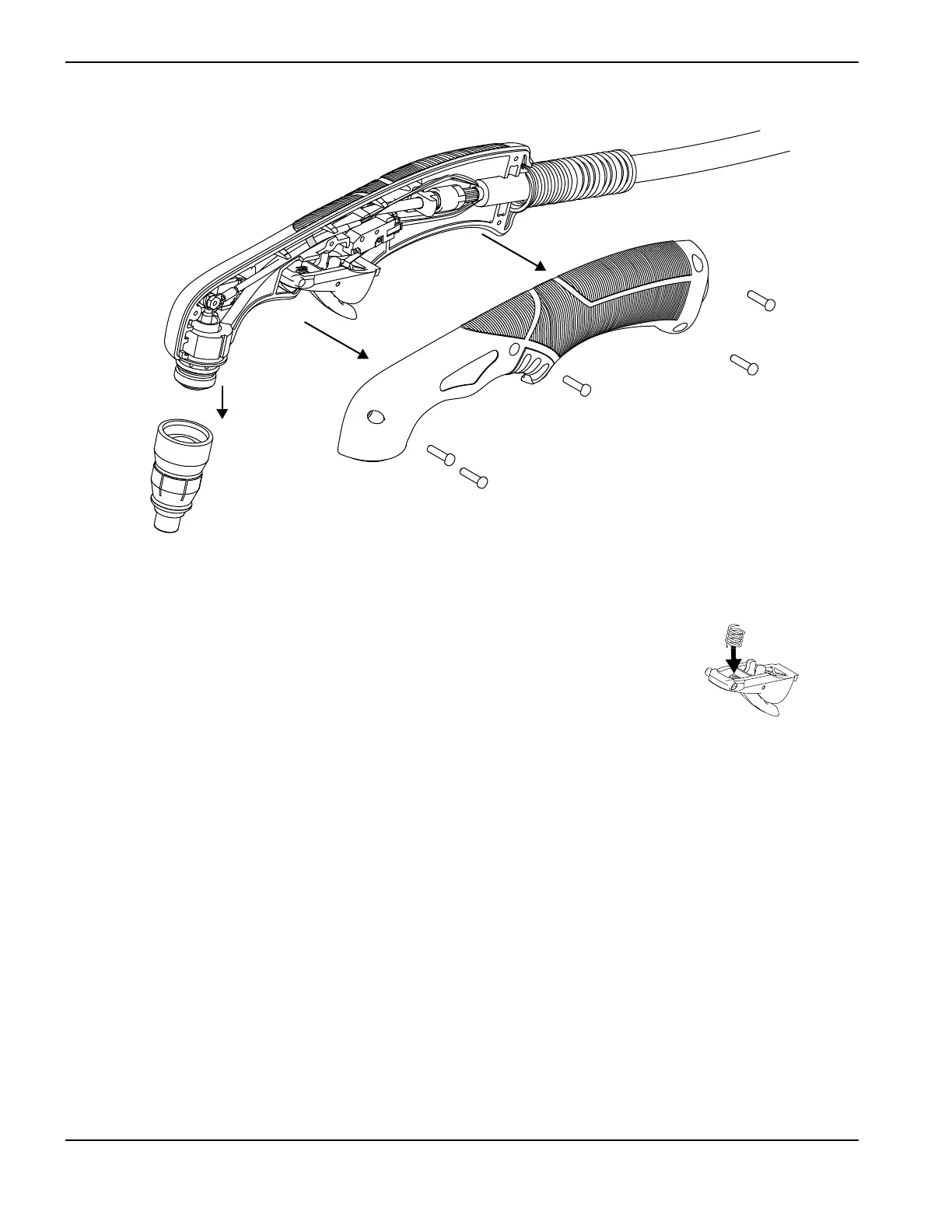
Figure 99
6. While holding the spring in place, slide the trigger and spring up and out of the handle.
7. Compress the new trigger spring into the front half of the new trigger. Slide the trigger
and spring into place.
8. Being careful that the handle does not pinch the wires, align the left half of the handle with
the right half. Make sure the trigger pivots are both located in the trigger pivot holes. See
Figure 98 on page 190.
9. Install the handle screws.
10. Pull the trigger to make sure it is positioned correctly in the torch handle
11 . Install the consumables.
12. Reconnect the power cord, and set the power switch to ON (I).